Device Identification
Error rendering macro 'excerpt-include': User
'712020:515aa595-e304-41f3-886a-d9b6b0b7f5a3'does not have permission to view the page'DEV:Wave Devices Images'.
Terminology
- Device – In this document, the term “Device” is used to refer to the Shelly Qubino device that is a subject of this guide.
- Gateway (GW) – A Z-Wave™ gateway, also referred to as a Z-Wave™ controller, Z-Wave™ main controller, Z-Wave™ primary controller, Z-Wave™ hub, etc., is a device that serves as a central hub for a Z-Wave™ smart home network. The term “gateway” is used in this document.
- S button – The Z-Wave™ Service button, located on Z-Wave™ devices and is used for various functions such as adding (inclusion), removing (exclusion), and resetting the device to its factory default settings. The term "S button" is used in this document.
- Adding/Inclusion – The process of adding a Z-Wave device to a Z-Wave network - gateway. The words included, added, etc., are used in this regard.
- Removing/Exclusion – The process of removing a Z-Wave device from a Z-Wave network - gateway. The words excluded, removed, etc., are used in this regard.
Short Description
Error rendering macro 'excerpt-include': User
'712020:515aa595-e304-41f3-886a-d9b6b0b7f5a3'does not have permission to view the page'DEV:About the Device'.
Switch/Push-button connected to input terminal SW (SW1)
If the SW (SW1) is configured as a switch (default), each toggle of the switch will change the output O (O1) state to the opposite state – on, off, on, etc. If the SW (SW1) is configured as a push-button in the Device settings, each press of the push-button will change the output O (O1) state to the opposite state – on, off, on, etc.
Switch connected to input terminal SW (SW1)
If the SW (SW1) is configured as a switch (default), each toggle of the switch will change the output O (O1) state to the opposite state – on, off, on, etc.
- Change switch position once: Change the state of the output O (O1) state to the opposite state and send the command to the associated devices in associated groups 2 and 3 (check chapter Z-Wave Association).
Switch-memory connected to input terminal SW (SW1)
If the SW (SW1) is configured as a switch-memory, then:
- Switching to Close switch-memory contact: Change the state of the output state O (O1) to the On state and send command to the associated devices in associated groups 2 and 3 (check chapter Z-Wave Association).
- Switching to Open switch-memory contact: Change the state of the output state O (O1) to the Off state and send command to the associated devices in associated groups 2 and 3 (check chapter Z-Wave Association).
Push-button connected to input terminal SW (SW1)
If the SW (SW1) is configured as a push-button in the Device settings, each press of the push-button changes the output state O (O1) to the opposite – ON, OFF, ON, etc.
- Short press: Change the state of the output state O (O1) to the opposite one and send command to the associated devices in associated groups 2 and 3 (check chapter Z-Wave Association).
- Hold: Send command to the associated devices in associated group 3 (check chapter Z-Wave Association).
- Release: Send command to the associated devices in associated group 3 (check chapter Z-Wave Association).
Switch/Push-button connected to input terminal SW2
If the SW2 is configured as a switch (default), each toggle of the switch will change the output O2 state to the opposite state – on, off, on, etc. If the SW2 is configured as a push-button in the Device settings, each press of the push-button will change the output O2 state to the opposite state – on, off, on, etc.
Switch connected to input terminal SW2
If the SW2 is configured as a switch (default), each toggle of the switch will change the output state O2 to the opposite state – ON, OFF, ON, etc.
- Change switch position once: Change the state of the output state O2 to the opposite one and send command to the associated devices in associated groups 4 and 5 (check chapter Z-Wave Association).
Switch-memory connected to input terminal SW2
If the SW2 is configured as a switch-memory, then:
- Switching to Close switch-memory contact: Change the state of the output state O2 to the On state and send command to the associated devices in associated groups 4 and 5 (check chapter Z-Wave Association).
- Switching to Open switch-memory contact: Change the state of the output state O2 to the Off state and send command to the associated devices in associated groups 4 and 5 (check chapter Z-Wave Association).
Push-button connected to input terminal SW2
If the SW2 is configured as a push-button in the Device settings, each press of the push-button changes the output state O2 to opposite – ON, OFF, ON, etc.
- Short press: Change the state of the output state O2 to the opposite one and send command to the associated devices in associated groups 4 and 5 (check chapter Z-Wave Association).
- Hold: Send command to the associated devices in associated group 4 (check chapter Z-Wave Association).
- Release: Send command to the associated devices in associated group 5 (check chapter Z-Wave Association).
Switch/Push-button connected to input terminal SW3
If the SW3 is configured as a switch (default), each toggle of the switch will change the output O3 state to the opposite state – on, off, on, etc. If the SW3 is configured as a push-button in the Device settings, each press of the push-button will change the output O3 state to the opposite state – on, off, on, etc.
Switch connected to input terminal SW3
If the SW3 is configured as a switch (default), each toggle of the switch will change the output state O3 to the opposite state – ON, OFF, ON, etc.
- Change switch position once: Change the state of the output state O3 to the opposite one and send command to the associated devices in associated groups 6 and 7 (check chapter Z-Wave Association).
Switch-memory connected to input terminal SW3
If the SW3 is configured as a switch-memory, then:
- Switching to Close switch-memory contact: Change the state of the output state O3 to the On state and send command to the associated devices in associated groups 6 and 7 (check chapter Z-Wave Association).
- Switching to Open switch-memory contact: Change the state of the output state O3 to the Off state and send command to the associated devices in associated groups 6 and 7 (check chapter Z-Wave Association).
Push-button connected to input terminal SW3
If the SW3 is configured as a push-button in the Device settings, each press of the push-button changes the output state O3 to opposite – ON, OFF, ON, etc.
- Short press: Change the state of the output state O3 to the opposite one and send command to the associated devices in associated groups 6 and 7 (check chapter Z-Wave Association).
- Hold: Send command to the associated devices in associated group 6 (check chapter Z-Wave Association).
- Release: Send command to the associated devices in associated group 7 (check chapter Z-Wave Association).
Main Applications
- Residential
- MDU (Multi Dwelling Units – apartments, condominiums, hotels, etc.)
- Light commercial (small office buildings, small retail/restaurant/gas station, etc.)
- Government/municipal
- University/college
- Farming
Integrations
Shelly Qubino Wave devices are developed on the world's leading technology for smart homes – Z-Wave.
This means Shelly Qubino Wave works with all certified gateways supporting Z-Wave communication protocol.
To make sure the functions of Shelly Qubino Wave products are supported on your gateway, we are regularly executing compatibility tests of our devices with different Z-Wave gateways.
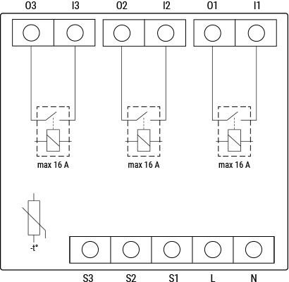
Simplified Internal Schematics
Device Electrical Interfaces
Inputs
Error rendering macro 'excerpt-include': User
'712020:515aa595-e304-41f3-886a-d9b6b0b7f5a3'does not have permission to view the page'DEV:Device electrical interfaces'.
Error rendering macro 'excerpt-include': User
'712020:515aa595-e304-41f3-886a-d9b6b0b7f5a3'does not have permission to view the page'DEV:Device electrical interfaces'.
Error rendering macro 'excerpt-include': User
'712020:515aa595-e304-41f3-886a-d9b6b0b7f5a3'does not have permission to view the page'DEV:Device electrical interfaces'.
Outputs
Error rendering macro 'excerpt-include': User
'712020:515aa595-e304-41f3-886a-d9b6b0b7f5a3'does not have permission to view the page'DEV:Device electrical interfaces'.
Connectivity
Z-Wave – Unsecure, S0 Security, S2 Unauthenticated Security, S2 Authenticated Security
Safety Features
Overheat protection
Supported Load Types
Error rendering macro 'excerpt-include': User
'712020:515aa595-e304-41f3-886a-d9b6b0b7f5a3'does not have permission to view the page'DEV:Supported load types'.
Error rendering macro 'excerpt-include': User
'712020:515aa595-e304-41f3-886a-d9b6b0b7f5a3'does not have permission to view the page'DEV:Supported load types'.
Error rendering macro 'excerpt-include': User
'712020:515aa595-e304-41f3-886a-d9b6b0b7f5a3'does not have permission to view the page'DEV:Supported load types'.
User Interface
Unable to render
{include}
The included page could not be found.
LED Signalisation
Click to see LED signalisation
Removed/Excluded
The LED will be blinking blue in Mode 1 for 10 min after every power cycle and 10 min after S button pressed.

Added/Included
The LED will be blinking green in Mode 1 for 10 min after every power cycle and 10 min after S button pressed.

Settings in progress
Factory reset and reboot
During factory reset, the LED will turn solid green for approx. 1 sec, then the blue and red LED will be blinking 0.1s On, 0.1s Off for about 2 sec.Adding / Removing
During adding or removing, the LED will be blinking blue in Mode 2.
Firmware updating OTA
During the OTA update, the LED will be blinking blue and red in Mode 2.
Checking power supply 230 V AC frequency or 24 V DC voltage
During checking the power supply, the LED will be blinking blue and red in Mode 5.
Settings mode with S button
Adding / Removing menu selected
When the menu is selected, the LED will be on blue, for maximum of 10 seconds.Adding / Removing menu – while pressing S-button – Add/Remove process selected
When the menu is executing, the LED will be blinking blue in Mode 3.
Factory reset menu selected
When the menu is selected, the LED will be on red, for maximum of 10 seconds.Factory reset – while pressing S-button – Factory reset process selected
When the menu is executing, the LED will be blinking red in Mode 3.
Alarm Mode
Overheat detected
The LED will be blinking red in Mode 4: 2x – 0.2s On, 0.2s Off, 0.2s On, 0.2s Off, 2s Off – repeating this sequence.
LED Blinking Modes
Click to see the LED blinking modes
Error rendering macro 'excerpt-include': User
'712020:515aa595-e304-41f3-886a-d9b6b0b7f5a3'does not have permission to view the page'DEV:LED_Signalization'.
Specifications
Error rendering macro 'excerpt-include': User
'712020:515aa595-e304-41f3-886a-d9b6b0b7f5a3'does not have permission to view the page'DEV:Technical Specifications'.
Basic Wiring Diagram
> Error rendering macro 'excerpt-include': User '712020:515aa595-e304-41f3-886a-d9b6b0b7f5a3' does not have permission to view the page 'DEV:Wiring diagrams'. | > Error rendering macro 'excerpt-include': User '712020:515aa595-e304-41f3-886a-d9b6b0b7f5a3' does not have permission to view the page 'DEV:Wiring diagrams'. |
Legend
Unable to render
{include}
The included page could not be found.
About Z-Wave®
Adding and Removing the Device to a Z-Wave® Network
Click to see how to add, remove and reset the Device
Unable to render
{include}
The included page could not be found.
Z-Wave® Security and Device Specific Key (DSK)
Click to see about the Security and the DSK
The Device supports the latest Security 2 (S2) feature. S2 is handled by the Strong AES 128 Encryption protocol, which means that the S2 makes Z-Wave® the most secure IoT (Internet of Things) security platform out there. To fully utilize the product and its Security 2 feature, a Security 2-enabled Z-Wave® gateway must be used.
Authenticated Control
- Out-Of-Band DSK for inclusion
- May be used by most implementations
The Device also supports Security 2 Authenticated, Unauthenticated, and Unsecure inclusion.
Note! When adding the Device to a Z-Wave® network with a gateway supporting Security 2 (S2), the PIN Code of the Z-Wave® Device Specific Key (DSK) is required. The unique DSK code is printed on the DSK label on the side of the Device and a copy is inserted in the packaging, which must not be lost. Do not remove the DSK label from the product. As a backup measure, use the label in the packaging.
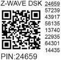
The first five digits of the key are highlighted or underlined to help the user identify the PIN Code part of the DSK text. The DSK is additionally represented with a QR Code as shown on the image.
DSK label and QR code (example)
A joining node requesting to join the S2 Access Control Class or the S2 Authenticated Class will obfuscate its Public Key by setting the bytes 1..2 to zeros (0x00) before transferring its key via RF.
The DSK may be used for out-of-band (OOB) authentication.
- The including gateway may use a QR code scanning device to read the entire DSK of the joining device and match it with the obfuscated public key received via RF from the joining device.
Z-Wave® Parameters
Click here to see the Z-Wave Parameters
Unable to render
{include}
The included page could not be found.
Z-Wave® Command Classes
Click to see the Z-Wave Command Classes
Unable to render
{include}
The included page could not be found.
Z-Wave® Notifications Command Class
Click to see the Z-Wave Notification Command Class
Unable to render
{include}
The included page could not be found.
Z-Wave® Associations
Click to see the Z-Wave Associations
Unable to render
{include}
The included page could not be found.
Z-Wave® Important Disclaimer
Z-Wave® wireless communication may not always be 100% reliable. This Device should not be used in situations in which life and/or valuables are solely dependent on its functioning. If the Device is not recognized by your gateway or appears incorrectly, you may need to change the Device type manually and ensure that your gateway supports Z-Wave Plus™ multi-level devices.
Troubleshooting
For troubleshooting please visit our support portal: Support
Compatibility
| Wave Pro 3 | functions - reports | | ----------------------------- | ----------------------- | -------- | -------- | ----------- | ----------- | ----------- | --------------------------------------------------------------------------------------------------- | | Gateway | On/Off 1 | On/Off 2 | On/Off 3 | SW On/Off 1 | SW On/Off 2 | SW On/Off 3 | Notes | | Home Assistant | ✅ | ✅ | ✅ | ✅ | ✅ | ✅ | | | Fibaro - HC 3 / Wave engine 3 | ✅ | ✅ | ✅ | ✅ | ✅ | ✅ | | | Homey | ✅ | ✅ | ✅ | ✅ | ✅ | ✅ | *H | | Homee Gen 7 | ✅ | ✅ | ✅ | ✅ | ✅ | ✅ | | | Homee Gen 5 | TBD | TBD | TBD | TBD | TBD | TBD | *1, *2 | | Smart Things | TBD | TBD | TBD | TBD | TBD | TBD | with the Shelly Wave edge driver | | Vera Ezlo | ✅ | ✅ | ✅ | ✅ | ✅ | ✅ | | | Cozify | ✅ | ✅ | ✅ | ✅ | ✅ | ✅ | |
Notes:
H – Troubles with reports can be solved with this solution.
Function Meaning
| Function | Meaning / tested |
|---|---|
| On/Off | if device respond to the app UI On/Off command |
| SW On/Off | if device reports On/Off changes by SW input |
| Dimming | if device respond to app UI dimming command |
| SW Dimming | if device report dimming state change by SW input |
| Watts | if Watts are reported (unsolicited) |
| kWh | if kWh are reported (unsolicited) |
| Up/Down | if device respond to the app UI Up/Down command |
| SW Up/Down | if device reports Up/Down changes by SW input |
| Slats | if the slats respond to the app UI command |
| SW Slats | if the slats report the changes done by SW |
| D control | detached mode if device reports scene commands single press, double press,… |
| D Binary | detached mode if the device reports binary On/Off by SW input |
| Sensor # | Is the sensor report visualized in the gateway, type of sensor in the notes |
Legend
| Symbol | State |
|---|---|
| Working / Possible | |
| Not Working / Not Possible | |
| P | Partially |
| N/T | Not Tested |
| TBD | To be done |
Gateway Guides
You may find useful guides on gateways in the Z-Wave Shelly Knowledge base.
Compliance
- Shelly Wave Pro 3 multilingual EU declaration of conformity 2025-07-30
- Wave Pro 3 UK PSTI ACT Statement of compliance