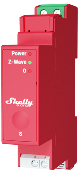
Shelly Wave Pro 1PM – Device Documentation
Note: The product line known as "Shelly Qubino Wave" will now be referred to as "Shelly Wave". This name change will not impact the functionality of any devices. The only modification will be the use of the new name in all future documentation.
Device Identification
- Device: Wave Pro 1PM
- AUS Part number / Ordering Code: QPSW-0A1P16AU
- Z-Wave Product type ID:
0x0002 - Z-Wave Product ID:
0x008B - Z-Wave Manufacturer: Shelly Europe Ltd.
- Z-Wave Manufacturer ID:
0x0460
Terminology
| Term | Definition |
|---|---|
| Device | In this document, the term “Device” refers to the Shelly Qubino device being discussed. |
| Gateway | A Z-Wave® gateway (also called Z-Wave® controller, main controller, primary controller, or hub) that serves as the central hub for a Z-Wave® smart home network. |
| S button | The Z-Wave® Service button located on Z-Wave® devices, used for inclusion, exclusion, and factory reset. |
Short Description
The Wave Pro 1PM is a DIN rail-mounted smart switch with power measurement. It controls the on/off function for one electrical load up to 16 A, and supports both switches (default) and push-buttons.
Switch Connected to Input Terminal SW (SW1)
If configured as a switch (default):
- One toggle: Changes output O (O1) state (on → off, off → on), sends command to associated devices in groups 2 and 3.
- Two toggles within 500ms: Interpreted as "double press", sends command to dimmers, shutters, etc., in groups 2 and 3.
Switch-Memory Connected to Input Terminal SW (SW1)
If configured as switch-memory:
- Close contact: Output O (O1) turns ON and sends command to associated devices in groups 2 and 3.
- Open contact: Output O (O1) turns OFF and sends command to associated devices in groups 2 and 3.
Push-Button Connected to Input Terminal SW (SW1)
If configured as a push-button:
- Short press: Toggles output O (O1) state (on ↔ off), sends command to groups 2 and 3.
- Hold: Sends command to group 3.
- Release: Sends command to group 3.
Switching On/Off Load Connected to O (O1)
The load connected to O (O1) can be switched via:
- Z-Wave commands
- Automatic switching (via Parameters No. 19 and 20)
- Pressing the switch/push-button SW (SW1): toggles load state
Main Applications
- Residential
- MDU (Multi Dwelling Units: apartments, condos, hotels)
- Light commercial (small offices, retail, restaurants, gas stations)
- Government / Municipal
- University / College
Integrations
Shelly Wave devices are built on Z-Wave, the world’s leading smart home technology. They work with all certified gateways supporting the Z-Wave protocol.
We regularly test compatibility across various Z-Wave gateways to ensure full feature support.
Simplified Internal Schematics
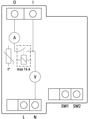
Device Electrical Interfaces
Inputs
- 2 switch/button inputs on screw terminals
- 2 power supply inputs on screw terminals: 2 N (+) and 3 L (−)
- 1 relay input on screw terminal
Outputs
- 1 relay output with power measurement on screw terminal
Connectivity
- Z-Wave: Unsecure, S0 Security, S2 Unauthenticated Security, S2 Authenticated Security
Safety Features
Overheat Protection
- If temperature exceeds 80°C for more than 5 seconds, the device:
- Turns off its own relay
- Sends a Notification Report to the gateway ("Overheat detected")
- LED reacts accordingly (see LED blinking modes)
Reset conditions:
- Power cycle
- Short press on S button
- Press any switch/push-button on SW (SW1, SW2, etc.)
✅ Note: Overheat protection is always active and cannot be disabled.
More details: Notification for Overheat Detected
Overcurrent Protection
- If current exceeds 16A + 10% (17.6A) for more than 5 seconds, the device:
- Turns off its relay
- Sends a Notification Report ("Over-current detected")
- LED blinks accordingly
Reset conditions:
- Power cycle
- Short press on S button
- Press any switch/push-button on SW (SW1, SW2, etc.)
✅ Note: Overcurrent protection is always active and cannot be disabled.
More details: Notification for Over-current Detected
Overvoltage Protection
- Valid for standard 230 V AC supply.
- If voltage exceeds 278 V AC (240V +15%) for more than 5 seconds, the device:
- Turns off its relay
- Sends a Notification Report ("Overvoltage detected")
- LED blinks accordingly
Reset conditions:
- Power cycle
- Short press on S button
- Press any switch/push-button on SW (SW1, SW2, etc.)
✅ Note: Overvoltage protection is always active and cannot be disabled.
More details: Notification for Overvoltage Detected
Supported Load Types
- Resistive (incandescent bulbs, heating devices)
- Capacitive (capacitor banks, electronic equipment, motor start capacitors)
- Inductive with RC Snubber (LED drivers, transformers, fans, refrigerators, air conditioners)
User Interface
S Button and Operating Modes
- Normal mode
- Setting in progress mode
- Setting mode (with S button)
- Used for inclusion, exclusion, factory reset, etc.
- Limited duration; automatically reverts to Normal mode after procedure.
Entering Setting Mode:
- Quickly press and hold the S button until the LED turns solid blue.
- Additional quick press → cycles through menu options.
- Menu timeout: 10 seconds before returning to Normal mode.
S Button Functions
- Manually add device to Z-Wave network
- Manually remove device from Z-Wave network
- Factory reset device
LED Signalisation
| Mode | Status | Meaning |
|---|---|---|
| Mode 1 | 0.5s On / 2s Off | Normal operation (blue = excluded, green = included) |
| Mode 2 | 0.5s On / 0.5s Off | Adding/removing, OTA update, power check |
| Mode 3 | 0.1s On / 0.1s Off | Executing action (add/remove/factory reset) |
| Mode 4 | (1–7 times) 0.2s On/Off + 2s Off | Alarm states (overcurrent, overheat, overvoltage, etc.) |
| Mode 5 | 0.2s On blue / 0.2s On red | Power supply check (AC frequency or DC voltage) |
Alarm LED Patterns:
| Alarm | Pattern | Description |
|---|---|---|
| Overcurrent detected | 1x: 0.2s On / 0.2s Off, 2s Off | Repeats |
| Overheat detected | 2x: 0.2s On / 0.2s Off, 2s Off | Repeats |
| Power supply fault | 3x: 0.2s On / 0.2s Off, 2s Off | Repeats |
| Overvoltage detected | 7x: 0.2s On / 0.2s Off, 2s Off | Repeats |
🔔 All alarms trigger relay OFF and send notification to gateway.
Specifications
⚠️ Error rendering macro 'excerpt-include': User does not have permission to view the page 'DEV:Technical Specifications'.
Basic Wiring Diagram
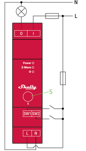
Legend
| Terminal | Function | Wire | Purpose |
|---|---|---|---|
| N | Neutral terminal | N | Neutral wire |
| L | Live terminal (110–240 V AC) | L | Live (110–240 V AC) wire |
| SW1 | Switch/push-button input (controls O) | — | Control input |
| SW2 | Switch/push-button input | — | Optional control input |
| I | Load circuit input | — | Input side of load |
| O | Load circuit output | — | Output side of load |
About Z-Wave®
Adding the Device to a Z-Wave® Network (Inclusion)
⚠️ Note: All outputs (O, O1, etc.) will briefly turn on/off during successful inclusion/exclusion.
SmartStart Inclusion
- Scan QR code on device label using gateway app.
- Add DSK to provisioning list.
- Connect device to power.
- Blue LED blinking in Mode 1 → not added.
- Auto-inclusion starts within seconds.
- Blue LED blinks in Mode 2 during process.
- Green LED blinks in Mode 1 if successful.
Adding with S Button
- Connect device to power.
- Check blue LED blinking in Mode 1.
- Enable add/remove mode on gateway.
- Press and hold S button until LED turns solid blue.
- Release, then press & hold (>2s) until LED blinks in Mode 3 → Learn mode starts.
- Blue LED blinks in Mode 2 during adding.
- Green LED blinks in Mode 1 if successful.
⏱️ Setting mode timeout: 10 seconds
Adding with Switch/Push-Button
- Connect device to power.
- Confirm blue LED blinking in Mode 1.
- Enable add/remove mode on gateway.
- Toggle SW terminal 3 times within 3 seconds → puts device in Learn mode.
- Blue LED blinks in Mode 2 during process.
- Green LED blinks in Mode 1 if successful.
📌 Learn mode: State allowing device to receive network info from gateway.
Removing the Device from a Z-Wave® Network (Exclusion)
⚠️ Note: Custom settings remain unchanged; only network association is removed.
Removing with S Button
- Connect device to power.
- Confirm green LED blinking in Mode 1 → device is added.
- Enable add/remove mode on gateway.
- Press and hold S button until LED turns solid blue.
- Release, then press & hold (>2s) until LED blinks in Mode 3 → Learn mode starts.
- Blue LED blinks in Mode 2 during removal.
- Blue LED blinks in Mode 1 if successful.
⏱️ Setting mode timeout: 10 seconds
Removing with Switch/Push-Button
- Connect device to power.
- Confirm green LED blinking in Mode 1.
- Enable add/remove mode on gateway.
- Toggle SW terminal 3 times within 3 seconds → Learn mode.
- Blue LED blinks in Mode 2 during removal.
- Blue LED blinks in Mode 1 if successful.
Factory Reset
General
After reset, all custom parameters (kWh, associations, routing, etc.) revert to default. HOME ID and NODE ID are deleted.
💡 Use only when gateway is missing or inoperable.
With S Button
- Press and hold S button until LED turns solid blue.
- Press S button repeatedly until LED turns solid red.
- Press and hold (>2s) S button until red LED blinks in Mode 3 → reset begins.
- During reset: LED turns solid green (~1s), then blue/red blink in Mode 3 (~2s).
- Blue LED blinking in Mode 1 indicates success.
With Switch/Push-Button
⚠️ Only possible within first minute after power-up.
- Connect device to power.
- Toggle SW terminal 5 times within 3 seconds.
- LED turns solid green (~1s), then blue/red blink in Mode 3 (~2s).
- Blue LED blinking in Mode 1 indicates success.
Remotely via Parameter No. 120
Set Parameter 120 to 1431655765 (hex 0x55555555) to trigger remote factory reset.
✅ After reset, parameter resets to
0.
Z-Wave® Security and Device Specific Key (DSK)
- Supports Security 2 (S2) with AES-128 encryption.
- Requires S2-enabled gateway for full security.
- Uses Out-of-Band DSK authentication.
- PIN Code (first 5 digits) required during S2 inclusion.
📌 DSK Label Example:
- Printed on device side and inside packaging.
- Include QR code for scanning.
- Do not remove label.
🔐 Important: Never lose the DSK label.
Z-Wave® Parameters
| Parameter | Description | Default | Values |
|---|---|---|---|
| 1 – SW (SW1) Switch Type | Defines behavior of switch on SW1 | 2 | 0: momentary, 1: toggle (contact closed=ON), 2: toggle (state changes) |
| 2 – SW2 Switch Type | Same for SW2 terminal | 2 | 0: momentary, 1: toggle (closed=ON), 2: toggle (state changes) |
| 17 – Restore State After Power Failure | Save last state after outage? | 0 | 0: yes, 1: no (remains off) |
| 19 – Auto OFF Timer (O1) | Schedule auto-off after ON | 0 | 0: disabled, 1–32535: sec or ms (see Param 25) |
| 20 – Auto ON Timer (O1) | Schedule auto-on after OFF | 0 | 0: disabled, 1–32535: sec or ms |
| 23 – O (O1) Contact Type | Relay contact: NO or NC | 0 | 0: NO, 1: NC |
| 25 – Timer Units (sec/ms) | Set timer resolution | 0 | 0: seconds, 1: milliseconds |
| 36 – Power Report Change (%) | Min % change to report power | 50 | 0: disabled, 1–100% |
| 39 – Min Time Between Reports (O1) | Min interval between reports | 30 | 0: disabled, 1–120 seconds |
| 91 – Water Alarm Response | Action on water alarm | 0 | 0: none, 1: open relay, 2: close relay |
| 92 – Smoke Alarm Response | Action on smoke alarm | 0 | 0: none, 1: open, 2: close |
| 93 – CO Alarm Response | Action on CO alarm | 0 | 0: none, 1: open, 2: close |
| 94 – Heat Alarm Response | Action on heat alarm | 0 | 0: none, 1: open, 2: close |
| 120 – Factory Reset | Trigger reset | 0 | 0: no, 1431655765 (0x55555555) |
| 201–203 – Serial Number Parts | Read-only, hidden | Device-specific | 0x00000000 – 0x7FFFFFFF |
Z-Wave® Command Classes
| Class | Security |
|---|---|
| ASSOCIATION_V2 | [S0, S2]* |
| ASSOCIATION_GRP_INFO_V3 | [S0, S2]* |
| BASIC_V2 | [S0, S2]* |
| SWITCH_BINARY_V2 | [S0, S2]* |
| CONFIGURATION_V4 | [S0, S2]* |
| DEVICE_RESET_LOCALLY_V1 | [S0, S2]* |
| FIRMWARE_UPDATE_MD_V5 | [S0, S2]* |
| INDICATOR_V3 | [S0, S2]* |
| MANUFACTURER_SPECIFIC_V2 | [S0, S2]* |
| METER_V6 | [S0, S2]* |
| MULTI_CHANNEL_ASSOCIATION_V3 | [S0, S2]* |
| NOTIFICATION_V8 | [S0, S2]* |
| POWERLEVEL_V1 | [S0, S2]* |
| SECURITY_V1 | — |
| SECURITY_2_V1 | — |
| SUPERVISION_V1 | — |
| TRANSPORT_SERVICE_V2 | — |
| VERSION_V3 | [S0, S2]* |
| ZWAVEPLUS_INFO_V2 | — |
[S2] = Security S2 Command Class
Z-Wave® Notifications Command Class
Overheat Detected
| Field | Value |
|---|---|
| Notification Type Name | Heat Alarm |
| Value | 0x04 |
| Event | State |
| Notification Name | Overheat detected |
| Value | 0x02 |
| Version | V2 |
| Device Specific | Yes |
| LED Signalisation | See table |
| Device Reaction | Turn off output, send notification |
| Restore Action | Power cycle, S button press, SW press |
Over-current Detected O (O1)
| Field | Value |
|---|---|
| Notification Type Name | Power management |
| Value | 0x08 |
| Event | State |
| Notification Name | Over-current detected |
| Value | 0x06 |
| Version | V3 |
| Device Specific | Yes |
| LED Signalisation | See table |
| Device Reaction | Turn off O(1), send notification |
| Restore Action | Power cycle, S button press, SW press |
AC Mains Disconnected
| Field | Value |
|---|---|
| Notification Type Name | Power management |
| Value | 0x08 |
| Event | State |
| Notification Name | AC mains disconnected |
| Value | 0x02 |
| Version | V2 |
| Device Specific | Yes |
| LED Signalisation | See table |
| Device Reaction | Turn off all outputs, send notification |
| Restore Action | Power cycle, S button press, SW press |
Z-Wave® Associations
| Group | Nodes | Trigger | Commands | Notes |
|---|---|---|---|---|
| 1 (Lifeline) | 1 (Gateway) | Status, errors | INDICATOR_REPORT, DEVICE_RESET_LOCALLY_NOTIFICATION, SWITCH_BINARY_REPORT, NOTIFICATION_REPORT, METER_REPORT | Standard lifeline |
| 2 | 9 | SW1 (On/Off) | BASIC_SET ON/OFF | For basic switch control |
| 3 | 9 | SW1 (Dimming) | SWITCH_MULTILEVEL_START_LEVEL_CHANGE / STOP | For dimmer/slats |
| 4 | 9 | SW1 (On/Off) | BASIC_SET ON/OFF | Duplicate of group 2 |
| 5 | 9 | SW1 (Dimming) | SWITCH_MULTILEVEL_START_LEVEL_CHANGE / STOP | Duplicate of group 3 |
Z-Wave® Important Disclaimer
Z-Wave® communication may not be 100% reliable. Do not rely solely on this device for life-critical applications. If the device isn't recognized, manually change the device type and confirm gateway supports Z-Wave Plus™ multi-level devices.
Troubleshooting
For help, visit: Shelly Support Portal
Compatibility with Gateways
| Gateway | On/Off | SW On/Off | Watts | kWh | Notes |
|---|---|---|---|---|---|
| Home Assistant | ✅ | ✅ | ✅ | ✅ | |
| Fibaro HC3 / Z-Wave engine 3 | ✅ | ✅ | ✅ | ✅ | |
| Homey | ✅ | ✅ | ✅ | ✅ | |
| Homee Cube Gen 7 | ✅ | ✅ | ✅ | ✅ | |
| Homee Cube Gen 5 | ✅ | ⚠️ P*1 | ⚠️ ★*2 | ⚠️ ★*2 | *1 UI doesn’t reflect updates *2 W/kWh not reported |
| SmartThings | ✅ | ✅ | ✅ | ✅ | With Shelly Wave edge driver |
| Vera Ezlo | ✅ | ✅ | ✅ | ✅ | |
| Cozify | ✅ | ✅ | ✅ | ✅ |
🔍 Legend:
- ✅ = Working / Possible
- ⚠️ ★ = Not working / Not possible
- ⚠️ P = Partially
- N/T = Not Tested
- TBD = To Be Done
Gateway Guides
Useful guides: Shelly Knowledge Base – Z-Wave
Compliance
- Wave Pro 1PM Multilingual EU Declaration of Conformity (2025)
- Wave Pro 1PM UK PSTI ACT Statement of Compliance