Shelly Wave Pro 1 – Device Documentation
Note: The product line known as "Shelly Qubino Wave" will now be referred to as "Shelly Wave". This name change will not impact the functionality of any devices. The only modification will be the use of the new name in all future documentation.
Device Identification
- Device: Wave Pro 1
- EU Part number/Ordering Code: QPSW-0A1X16EU
- Z-Wave Product type ID:
0x0002 - Z-Wave Product ID:
0x008A - Z-Wave Manufacturer: Shelly Europe Ltd.
- Z-Wave Manufacturer ID:
0x0460
Terminology
- Device: In this document, the term “Device” refers to the Shelly Qubino device covered by this guide.
- Gateway: A Z-Wave® gateway (also called Z-Wave® controller, Z-Wave® main controller, Z-Wave® primary controller, or Z-Wave® hub). It acts as a central hub for a Z-Wave® smart home network. The term “gateway” is used here.
- S button: The Z-Wave® Service button located on Z-Wave® devices, used for functions like adding (inclusion), removing (exclusion), and resetting to factory defaults. The term “S button” is used throughout.
Short Description
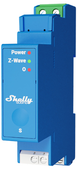
The Shelly Wave Pro 1 is a DIN rail-mountable smart switch with potential-free contacts. It controls the on/off function for one electrical load up to 16 A. Compatible with switches (default) and push-buttons.
Switch Connected to Input Terminal SW (SW1)
If SW (SW1) is configured as a switch (default):
- Each toggle changes the output O (O1) state: On → Off → On → etc.
Actions:
- Change switch position once: Toggle output O (O1) state and send command to associated devices in groups 2 and 3 (see Z-Wave Association).
Switch-Memory Connected to Input Terminal SW (SW1)
If SW (SW1) is configured as switch-memory:
- Closing contact: Output O (O1) turns ON, sends command to devices in groups 2 and 3.
- Opening contact: Output O (O1) turns OFF, sends command to devices in groups 2 and 3.
Push-Button Connected to Input Terminal SW (SW1)
If SW (SW1) is configured as a push-button:
- Each press toggles output O (O1): ON → OFF → ON → etc.
Actions:
- Short Press: Toggle output O (O1) state; send command to devices in groups 2 and 3.
- Hold: Send command to devices in group 3.
- Release: Send command to devices in group 3.
🔗 See Z-Wave Association for more details.
Switch/Push-Button Connected to Input Terminal SW2
If SW2 is configured as a switch (default):
- Each change in switch status sends an association command to:
- Group 4 (on/off), or
- Group 5 (SSLC – root single-channel device only) depending on current switch position.
🔗 Refer to Z-Wave Association chapter.
Switch-Memory Connected to Input Terminal SW2
If SW2 is configured as memory switch:
- Any state change sends an association command to group 4 (on/off) or group 5 (SSLC), based on the last remembered state after power loss.
🔗 See Z-Wave Association chapter.
Push-Button Connected to Input Terminal SW2
- Short Press: Toggles between ON/OFF commands; sends to group 4 (on/off) or group 5 (SSLC – root single-channel only).
- Hold: Sends command to initiate level adjustment for devices in group 5 (SSLC – root single-channel only).
- Release: Stops level adjustment for devices in group 5 (SSLC – root single-channel only).
🔗 See Z-Wave Association chapter.
Switching On/Off Load Connected to O (O1)
The load connected to O (O1) can be switched ON/OFF via:
- Z-Wave command
- Automatic switching enabled via Parameters No. 19 and 20
- Pressing the switch/push-button SW (SW1)
Main Applications
- Residential
- MDU (Multi Dwelling Units – apartments, condos, hotels, etc.)
- Light commercial (small offices, retail, restaurants, gas stations, etc.)
- Government/municipal
- University/college
- Farming
Integrations
Shelly Wave devices are built on Z-Wave, the world’s leading smart home technology.
This means they work with all certified Z-Wave gateways.
We regularly test compatibility across various gateways to ensure full functionality.
Simplified Internal Schematics
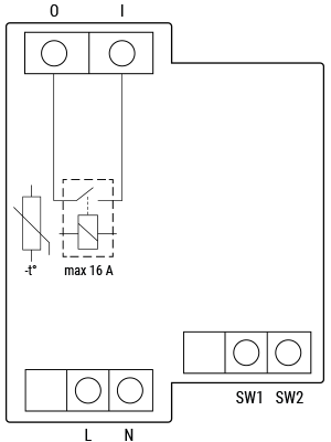
Device Electrical Interfaces
Inputs
- 2 switch/button inputs on screw terminals
- 1 potential-free contact relay input on screw terminal
- 2 power supply inputs on screw terminals: N, L
Outputs
- 1 potential-free contact relay output on screw terminal
Connectivity
Z-Wave: Unsecure, S0 Security, S2 Unauthenticated Security, S2 Authenticated Security
Safety Features
Overheat Protection
- Automatically switches off its own relay
- Sends Notification Report to the gateway ("Overheat detected")
- LED reacts accordingly (check blinking mode for "Overheat detected")
✅ Reset triggers: Power cycle, short press on S button, or pressing any switch/push-button on SW (SW1, SW2, etc.)
⚠️ Note: Overheat protection is always active and cannot be disabled.
🔗 See Notification for Overheat Detected for details.
Supported Load Types
- Resistive (incandescent bulbs, heating devices)
- Capacitive (capacitor banks, electronic equipment, motor start capacitors)
- Inductive with RC Snubber (LED drivers, transformers, fans, refrigerators, air conditioners)
User Interface
S Button and Operating Modes
- Normal mode
- “Setting in progress” mode
- Setting mode (with S button)
- Required to perform actions like inclusion, exclusion, factory reset.
- Limited time window; automatically returns to Normal mode after completion.
- Entering Setting Mode:
- Quickly press and hold the S button until LED turns solid blue.
- Additional quick press cycles through menu options.
- Menu timeout: 10 seconds before returning to Normal mode.
S Button Functions
- Manually add device to Z-Wave network
- Manually remove device from Z-Wave network
- Factory reset device
LED Signalisation
| State | LED Behavior |
|---|---|
| Removed/Excluded | Blinking blue in Mode 1 for 10 minutes after power cycle or S button press |
| Added/Included | Blinking green in Mode 1 for 10 minutes after power cycle or S button press |
| Factory Reset & Reboot | Solid green (~1 sec), then blue + red blinking (0.1s on/off) for ~2 sec |
| Adding / Removing | Blinking blue in Mode 2 |
| OTA Firmware Update | Blinking blue + red in Mode 2 |
| Power Supply Check | Blinking blue + red in Mode 5 |
| Menu Selected (Add/Remove) | Solid blue (max 10 sec) |
| Executing Add/Remove | Blinking blue in Mode 3 |
| Menu Selected (Factory Reset) | Solid red (max 10 sec) |
| Executing Factory Reset | Blinking red in Mode 3 |
| Overheat Detected | Blinking red in Mode 4: (0.2s On / 0.2s Off) × 1–6, then 2s Off |
📌 Click to view LED signalization images:
View LED Signalisation
LED Blinking Modes
| Mode | Blink Pattern |
|---|---|
| Mode 1 | 0.5s On / 2s Off |
| Mode 2 | 0.5s On / 0.5s Off |
| Mode 3 | 0.1s On / 0.1s Off |
| Mode 4 | (1–6 times) 0.2s On / 0.2s Off, then 2s Off |
| Mode 5 | 0.2s On (blue) / 0.2s On (red) |
Specifications
| Parameter | Value |
|---|---|
| Power Supply | 110–240 V AC, 50/60 Hz |
| Power Consumption | < 0.3 W |
| Max Switching Voltage (AC) | 240 V |
| Max Switching Current (AC) | 16 A |
| Max Switching Voltage (DC) | N/A |
| Max Switching Current (DC) | N/A |
| Overheating Protection | Yes |
| Power Measurement (W) | No |
| Communication Range | Up to 40 m indoors (131 ft.) – depends on conditions |
| Z-Wave® Repeater | Yes |
| CPU | Z-Wave® S800 |
| Z-Wave® Frequency Band | 868.4 MHz |
| Max Radio Power | < 25 mW |
| Dimensions (H × W × D) | 94 × 19 × 69 ±0.5 mm / 3.70 × 0.75 × 2.71 ±0.02 in |
| Weight | 60 g / 2.12 oz. |
| Mounting | DIN rail |
| Screw Terminal Torque | 0.4 Nm / 3.54 lbin |
| Conductor Cross Section |
- Green connector: 0.5–2.5 mm² / 20–14 AWG
- White connectors: 0.5–1.5 mm² / 20–16 AWG
| Stripped Length | - Green connector: 6–7 mm / 0.24–0.28 in
- White connectors: 5–6 mm / 0.20–0.24 in
| Shell Material | Plastic | | Color | Blue | | Ambient Temperature | -20°C to 40°C / -5°F to 105°F | | Humidity | 30% to 70% RH | | Max Altitude | 2000 m / 6562 ft. |
Basic Wiring Diagram
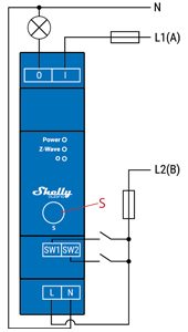
Legend
| Terminal | Function | Wire | Purpose |
|---|---|---|---|
| N | Neutral terminal | N | Neutral wire |
| L | Live terminal (110–240 V AC) | L1(A) | Load circuit live wire |
| SW | Switch/push-button input (controls O) | L2(B) | Device power supply live wire |
| SW2 | Switch/push-button input terminal | — | — |
| I | Load circuit input terminal | — | — |
| O | Load circuit output terminal | — | — |
About Z-Wave®
Adding the Device to a Z-Wave® Network (Inclusion)
💡 Note: All outputs (O, O1, etc.) will briefly turn on/off during successful addition/removal.
🔐 Security 2 (S2) Note: A 5-digit PIN from the Z-Wave® DSK label (on device and packaging) is required. Do not lose it.
SmartStart Inclusion
- Scan the QR code on the device using a SmartStart-capable gateway.
- Connect the device to power.
- If the blue LED blinks in Mode 1 → device not added.
- Addition starts automatically within seconds.
- Blue LED blinks in Mode 2 during inclusion.
- Green LED blinks in Mode 1 if successful.
Inclusion with S Button
- Connect to power.
- Confirm blue LED blinks in Mode 1.
- Enable add/remove mode on gateway.
- Hold S button until LED turns solid blue.
- Release, then hold >2 seconds until LED blinks in Mode 3 → starts Learn mode.
- Blue LED blinks in Mode 2 during process.
- Green LED blinks in Mode 1 upon success.
⏳ Timeout: 10 seconds in Setting mode before returning to Normal.
Inclusion with Switch/Push-Button
- Connect to power.
- Confirm blue LED blinks in Mode 1.
- Enable add/remove mode on gateway.
- Toggle switch/push-button on any SW terminal 3 times within 3 seconds → enters Learn mode.
- Blue LED blinks in Mode 2 during inclusion.
- Green LED blinks in Mode 1 if successful.
📌 Learn mode: State allowing device to receive network info from gateway.
Removing the Device from a Z-Wave® Network (Exclusion)
💡 Note: Custom settings remain unchanged. Only network membership is removed.
Removal with S Button
- Connect to power.
- Confirm green LED blinks in Mode 1 → device is added.
- Enable add/remove mode on gateway.
- Hold S button until LED turns solid blue.
- Release, then hold >2 seconds until LED blinks in Mode 3 → starts Learn mode.
- Blue LED blinks in Mode 2 during removal.
- Blue LED blinks in Mode 1 if successful.
⏳ Timeout: 10 seconds in Setting mode.
Removal with Switch/Push-Button
- Connect to power.
- Confirm green LED blinks in Mode 1.
- Enable add/remove mode on gateway.
- Toggle any SW terminal switch/push-button 3 times within 3 seconds → enters Learn mode.
- Blue LED blinks in Mode 2 during removal.
- Blue LED blinks in Mode 1 if successful.
Factory Reset
⚠️ After reset: All custom parameters, associations, routing, kWh data, etc., revert to default. HOME ID and NODE ID are deleted.
With S Button
- Hold S button until LED turns solid blue.
- Press S button repeatedly until LED turns solid red.
- Hold S button >2 seconds until red LED blinks in Mode 3 → starts reset.
- LED flashes solid green (~1s), then blue/red blinking (Mode 3) for ~2s.
- Blue LED blinks in Mode 1 → reset complete.
With Switch/Push-Button
⚠️ Only possible within first minute after power-up.
- Connect to power.
- Toggle any SW terminal switch/push-button 5 times within 3 seconds.
- LED flashes solid green (~1s), then blue/red blinking (Mode 3) for ~2s.
- Blue LED blinks in Mode 1 → reset complete.
Remote Factory Reset (via Gateway)
Set Parameter No. 120 = 1
Z-Wave® Security and Device Specific Key (DSK)
- Supports Security 2 (S2) using Strong AES-128 encryption.
- Requires S2-enabled gateway for full security.
- Supports:
- Out-of-band DSK inclusion
- Authenticated, Unauthenticated, and Unsecure inclusion
🔐 Important: The DSK PIN (first 5 digits) is printed on the side label and inside packaging. Never remove the label.
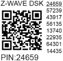
The DSK may also be scanned via QR code. During inclusion, the gateway verifies the obfuscated public key received via RF.
Z-Wave® Parameters
| Parameter | Description | Size | Default | Values |
|---|---|---|---|---|
| No. 1 – SW (SW1) Switch Type | Defines how SW1 is interpreted | 1 Byte | 2 | 0=Momentary, 1=Toggle (closed=ON), 2=Toggle (state change) |
| No. 2 – SW2 Switch Type | Defines how SW2 is interpreted | 1 Byte | 2 | 0=Push-button, 1=Toggle (closed=ON), 2=Toggle (state change) |
| No. 17 – Restore O (O1) After Power Failure | Whether to restore last state | 1 Byte | 0 | 0=Restore, 1=Do not restore (remains OFF) |
| No. 19 – Auto OFF Timer (O1) | Schedule auto-off after delay | 2 Bytes | 0 | 0=Disabled, 1–32535=seconds or milliseconds (see Param 25) |
| No. 20 – Auto ON Timer (O1) | Schedule auto-on after delay | 2 Bytes | 0 | 0=Disabled, 1–32535=seconds or milliseconds (see Param 25) |
| No. 23 – O (O1) Contact Type (NO/NC) | Relay contact type | 1 Byte | 0 | 0=Normally Open (NO), 1=Normally Closed (NC) |
| No. 25 – Timer Unit (s/ms) | Set timer units | 1 Byte | 0 | 0=Seconds, 1=Milliseconds |
| No. 91 – Water Alarm Response | Action on water alarm | 4 Bytes | 0 | 0=No action, 1=Open relay, 2=Close relay |
| No. 92 – Smoke Alarm Response | Action on smoke alarm | 4 Bytes | 0 | 0=No action, 1=Open relay, 2=Close relay |
| No. 93 – CO Alarm Response | Action on CO alarm | 4 Bytes | 0 | 0=No action, 1=Open relay, 2=Close relay |
| No. 94 – Heat Alarm Response | Action on heat alarm | 4 Bytes | 0 | 0=No action, 1=Open relay, 2=Close relay |
| No. 120 – Factory Reset | Trigger remote reset | 1 Byte | 0 | 0=No reset, 1=Perform reset |
| No. 201–203 – Serial Number Parts | Read-only device serial parts | 4 Bytes each | Device-specific | 0x00000000 – 0x7FFFFFFF |
⚙️ Parameters 201–203 are read-only and hidden under "Advanced" tag.
Z-Wave® Command Classes
- ASSOCIATION_V2 [S0, S2]*
- ASSOCIATION_GRP_INFO_V3 [S0, S2]*
- BASIC_V2 [S0, S2]*
- SWITCH_BINARY_V2 [S0, S2]*
- CONFIGURATION_V4 [S0, S2]*
- DEVICE_RESET_LOCALLY_V1 [S0, S2]*
- FIRMWARE_UPDATE_MD_V5 [S0, S2]*
- INDICATOR_V3 [S0, S2]*
- MANUFACTURER_SPECIFIC_V2 [S0, S2]*
- MULTI_CHANNEL_ASSOCIATION_V3 [S0, S2]*
- NOTIFICATION_V8 [S0, S2]*
- POWERLEVEL_V1 [S0, S2]*
- SECURITY_V1
- SECURITY_2_V1
- SUPERVISION_V1
- TRANSPORT_SERVICE_V2
- VERSION_V3 [S0, S2]*
- ZWAVEPLUS_INFO_V2
[S2] = Security 2 Command Class
Z-Wave® Notifications Command Class
Overheat Detected
| Field | Value |
|---|---|
| Notification Type Name | Heat Alarm |
| Notification Type Value | 0x04 |
| Event | State |
| Notification Name | Overheat detected |
| Notification Name Value | 0x02 |
| Version | V2 |
| LED Signalisation | Mode 4: Red blinking (0.2s On/Off), repeat every 2s |
| Device Reaction | Turns off output(s), sends notification |
| Restore Actions | Power cycle, short S button press, press any SW button |
🔗 See Notification Details
Z-Wave® Associations
| Group | Purpose | Nodes Allowed | Trigger | Supported Commands |
|---|---|---|---|---|
| Group 1 (Lifeline) | Status reporting | 1 (Gateway only) | Device status | INDICATOR_REPORT, DEVICE_RESET_LOCALLY_NOTIFICATION, SWITCH_BINARY_REPORT, NOTIFICATION_REPORT |
| Group 2 | SW1 control (Basic) | Up to 9 | SW1 state (On/Off) | BASIC_SET |
| Group 3 | SW1 control (Multilevel) | Up to 9 | Recommended: Push-button | SWITCH_MULTILEVEL_START_LEVEL_CHANGE, STOP_LEVEL_CHANGE |
| Group 4 | SW2 control (Basic) | Up to 9 | SW2 state (On/Off) | BASIC_SET |
| Group 5 | SW2 control (Multilevel) | Up to 9 | Recommended: Push-button | SWITCH_MULTILEVEL_START_LEVEL_CHANGE, STOP_LEVEL_CHANGE |
⚠️ Avoid network delays: limit to ≤5 devices per group.
Z-Wave® Important Disclaimer
Z-Wave® communication may not be 100% reliable. Do not rely solely on this device for life-critical applications. If the device isn't recognized or behaves incorrectly, manually verify the device type and ensure your gateway supports Z-Wave Plus™ multi-level devices.
Troubleshooting
For help, visit: Support Portal
Compatibility
| Gateway | On/Off | SW On/Off | Notes |
|---|---|---|---|
| Home Assistant | ✅ | ✅ | |
| Fibaro HC 3 / Z-Wave Engine 3 | ✅ | ✅ | |
| Homey | ✅ | ✅ | |
| Homee Cube Gen 7 | ✅ | ✅ | |
| Homee Cube Gen 5 | ✅ | ⚠️ | 1* UI does not reflect output changes |
| SmartThings | ✅ | ✅ | With Shelly Wave Edge Driver |
| Vera Ezlo | ✅ | ✅ | |
| Cozify | ✅ | ✅ |
1* Output changes but UI doesn’t update.
Legend
| Symbol | Meaning |
|---|---|
| ✅ | Working / Possible |
| ⚠️ | Not Working / Not Possible |
| P | Partially |
| N/T | Not Tested |
| TBD | To Be Done |
Function Definitions
| Function | Meaning |
|---|---|
| On/Off | Responds to app UI On/Off command |
| SW On/Off | Reports On/Off changes via SW input |
| Dimming | Responds to dimming command |
| SW Dimming | Reports dimming state via SW input |
| Watts | Reports power usage unsolicited |
| kWh | Reports energy consumption unsolicited |
| Up/Down | Responds to Up/Down command |
| SW Up/Down | Reports Up/Down changes via SW input |
| Slats | Responds to slat control command |
| SW Slats | Reports slat changes via SW input |
| D Control | Reports scene commands (single/double press, etc.) in detached mode |
| D Binary | Reports binary On/Off via SW input in detached mode |
| Sensor # | Sensor visualization in gateway; note type |
Gateway Guides
Find useful guides at the Shelly Knowledge Base
Compliance
- Wave Pro 1 Multilingual EU Declaration of Conformity (2025)
- Wave Pro 1 UK PSTI ACT Statement of Compliance