Shelly Pro 1PM v.1 is a modification of Shelly Pro 1PM (SPSW-001PE16EU)
Shelly Pro 1PM v.0 is now obsolete and out of sale.
Download Shelly Pro 1PM multi-language printed user manual
Differences with Shelly Pro 1PM v.0 are marked by the ≠ symbol in the text below.
Main changes:
- Power supply: no more 12 VDC option.
- Connectors: 3-terminal connectors are replaced by 2-terminal ones.
- PCBs: relay 2-layer PCBs are replaced by 4-layer ones for better thermal performance.
- LAN: improved high voltage electrical distances.
- Plastics shell: improved dielectric performance.
Device identification (≠)
- Device name: Shelly Pro 1PM v.1
- Device model: SPSW-201PE16EU
- Device SSID: ShellyPro1PM-XXXXXX
Short description
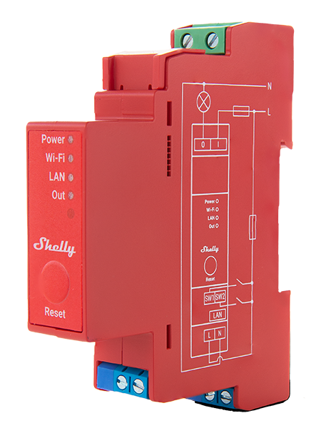
Shelly Pro 1PM is a DIN rail mountable smart switch with power measurement capabilities. Enhanced with all the gen2 firmware flexibility and LAN connectivity, it provides professional integrators with many more options for end customer solutions. It can work standalone in a local Wi-Fi network or it can also be operated through cloud home automation services.
Shelly Pro 1PM can be accessed, controlled and monitored remotely from any place where the user has internet connectivity, as long as the device is connected to a Wi-Fi router and the Internet.
Shelly Pro 1PM has an embedded Web Interface which can be used to monitor and control the device, as well as adjust its settings.
Main applications
- Residential
- MDU (Multi Dwelling Units - apartments, condominiums, hotels, etc.)
- Light commercial (small office buildings, small retail/restaurant/gas station, etc.)
- Government/municipal
- University/college
Integrations
- Alexa
- Samsung SmartThings
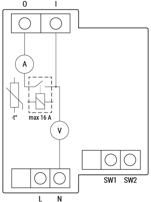
Simplified internal schematics (≠)
Device electrical interfaces
Inputs
- 2 switch/button inputs on screw terminals: SW1 and SW2
- 2 power supply inputs on screw terminals: 1 N and 1 L
- 1 relay input: I
Outputs
- 1 relay output: O
Ethernet port
- 1 RJ45 connector
⚠ CAUTION! Plug in or unplug the LAN cable only when the device is powered off! The LAN cable connector must not be metallic in the parts touched by the user to plug in or unplug the cable.
Add-on interface
- Shelly proprietary serial interface
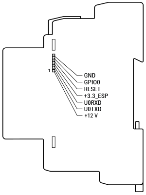
⚠ CAUTION! High voltage on the add-on interface when the device is powered!
Connectivity
- Ethernet
- Wi-Fi
- Bluetooth
Safety features
- Overheating protection
- Overvoltage protection
- Overcurrent protection
- Overpower protection
Supported load types
- Resistive (incandescent bulbs, heating devices)
- Capacitive (capacitor banks, electronic equipment, motor start capacitors)
- Inductive with RC Snubber (LED light drivers, transformers, fans, refrigerators, air-conditioners)
User interface
Inputs
- One tactile dome button
- Press and hold 5 sec to reboot.
- Press and hold 10 sec to factory reset.
Outputs
- LED indication
- Power (red): Red light indicator will be on if power supply is connected.
- Wi-Fi (varies):
- Blue light indicator will be on if in AP mode.
- Red light indicator will be on if in STA mode and not connected to a Wi-Fi network.
- Yellow light indicator will be on if in STA mode and connected to a Wi-Fi network. Not connected to Shelly Cloud or Shelly Cloud disabled.
- Green light indicator will be on if in STA mode and connected to a Wi-Fi network and to the Shelly Cloud.
- The light indicator will be flashing Red/Blue if OTA update is in progress.
- LAN (green): Green light indicator will be on if LAN is connected.
- Out (red): Red light indicator will be on if the Output relay is closed.
Specifications (≠)
| Type | Value |
|---|---|
| Physical | |
| Size (HxWxD): | 94×19×69 mm ±0.5 mm / 3.70×0.75×2.71 ±0.02 in |
| Weight: | 65 g |
| Mounting: | DIN rail |
| Screw terminals max torque: | 0.4 Nm / 3.54 lbin |
| Conductor cross section: | 0.5 to 2.5 mm² / 20 to 14 AWG (green connector) 0.5 to 1.5 mm² / 20 to 16 AWG (blue connectors) |
| Conductor stripped length: | 6 to 7 mm / 0.24 to 0.28 in (green connector) 5 to 6 mm / 0.20 to 0.24 in (blue connectors) |
| Shell material: | Plastic |
| Color: | Red |
| Environmental | |
| Ambient temperature: | -20 °C to 50 °C / -5 °F to 122 °F |
| Humidity: | 10 % to 90 % RH |
| Max. altitude: | 2000 m / 6562 ft |
| Electrical | |
| Power supply voltage AC: | 110 - 240 V |
| Power supply voltage DC: | N/A |
| Min. operating voltage AC: | 90 V |
| Max. operating voltage AC: | 264 V |
| Power consumption: | < 3 W |
| Neutral not needed: | No |
| Output circuits ratings | |
| Max switching voltage AC: | 240 V |
| Max switching voltage DC: | N/A |
| Max switching current AC: | 16 A |
| Max switching current DC: | N/A |
| Sensors, meters | |
| Voltmeter (AC): | Yes |
| Ammeter (AC): | Yes |
| Internal-temperature sensor: | Yes |
| Radio | |
| RF band: | 2400 - 2495 MHz |
| Max. RF power: | <20 dBm |
| Wi-Fi protocol: | 802.11 b/g/n |
| Wi-Fi Range: | Up to 30 m / 100 ft indoors and 50 m / 160 ft outdoors (Depends on local conditions) |
| Bluetooth Protocol: | 4.2 |
| Bluetooth Range: | Up to 10 m / 33 ft indoors and 30 m / 100 ft outdoors (Depends on local conditions) |
| MCU | |
| CPU: | ESP32-D0WDQ6 |
| Flash: | 8 MB |
| Firmware capabilities | |
| Schedules: | 20 |
| Webhooks (URL actions): | 20 with 5 URLs per hook |
| Scripting: | Yes |
| MQTT: | Yes |
| CoAP: | No |
Basic wiring diagram (≠)
| Resistive load | Inductive load and RC snubber |
|---|---|
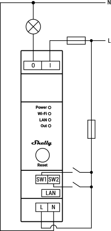 | 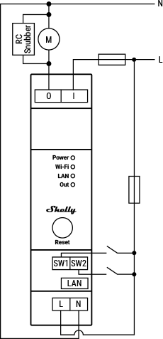 |
Legend
| Terminals | Description | Wires | Description |
|---|---|---|---|
| I | Load circuit input terminal | L | Live (110–240 V) wire |
| O | Load circuit output terminal | N | Neutral wire |
| SW1, SW2 | Switch/button input terminals | ||
| L | Live (110–240 V) terminal | ||
| N | Neutral terminal | ||
| LAN | Local Area Network RJ45 connector |
Shelly Smart Control
Shelly Web user interface
Troubleshooting
...
Components and APIs
Printed user guide
- Shelly Pro 1PM multilingual printed user and safety guide
- Ръководство за употреба и безопасност (Bulgarian)
Compliance
- Shelly Pro 1PM multilingual EU declaration of conformity 2025-07-21
- Shelly Pro 1PM UK PSTI ACT Statement of compliance
- Shelly PRO 1PM & 2PM AU NZ certificate for Suitability