Shelly Wave 1 Mini – Device Guide
Note: The product line known as "Shelly Qubino Wave" will now be referred to as "Shelly Wave". This name change will not impact the functionality of any devices. The only modification will be the use of the new name in all future documentation.
Device Identification
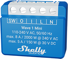
- Device name: Wave 1 Mini
- US Part number / Ordering Code: QMSW-0A1X8US
- Z-Wave Product type ID: 0x0002
- Z-Wave Product ID: 0x008E
- Z-Wave Manufacturer: Shelly Europe Ltd.
- Z-Wave Manufacturer ID: 0x0460
Terminology
- Device: In this document, the term “Device” refers to the Shelly Qubino device being discussed.
- Gateway: A Z-Wave® gateway (also called Z-Wave® controller, main controller, hub, etc.) that serves as the central hub for a Z-Wave® smart home network. The term “gateway” is used throughout this document.
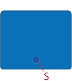
- S button: The Z-Wave® Service button located on Z-Wave® devices, used for functions like inclusion, exclusion, and factory reset. The term “S button” is used here.
Short Description
If SW (SW1) is configured as a switch (default), each toggle changes the output O (O1) state to the opposite — on → off → on → etc.
If SW (SW1) is configured as a push-button in the device settings, each press toggles the output O (O1) state — on → off → on → etc.
Switch Connected to Input Terminal SW (SW1)
When configured as a switch (default):
- Toggle once: Changes the output O (O1) state to the opposite and sends a command to associated devices in groups 2 and 3.
(See: Z-Wave Association)
Switch-Memory Connected to Input Terminal SW (SW1)
When configured as a switch-memory:
- Close contact: Output O (O1) turns ON → sends command to devices in groups 2 and 3.
- Open contact: Output O (O1) turns OFF → sends command to devices in groups 2 and 3.
(See: Z-Wave Association)
Push-Button Connected to Input Terminal SW (SW1)
When configured as a push-button:
- 1x click: Toggles output O (O1) state; sends command to devices in groups 2 and 3.
- 2x click (within 500ms): Interpreted as a double click → sends command to associated devices (dimmers, shutters, etc.) in groups 2 and 3.
- Hold: Sends command to devices in group 3.
- Release: Sends command to devices in group 3.
(See: Z-Wave Association)
Main Applications
- Residential
- MDU (Multi Dwelling Units – apartments, condos, hotels, etc.)
- Light Commercial (small offices, retail, restaurants, gas stations, etc.)
- Government / Municipal
- University / College
Integrations
Shelly Qubino Wave devices are built on Z-Wave, the world’s leading smart home technology.
This means they work with all certified gateways supporting the Z-Wave protocol.
We regularly test compatibility across various Z-Wave gateways to ensure full functionality.
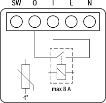
Simplified Internal Schematics
Device Electrical Interfaces
Inputs
- 1 switch/button input on screw terminal
- 1 potential-free contact relay input on screw terminal
- 2 power supply inputs on screw terminals: N, L
Outputs
- 1 potential-free contact relay output on screw terminal
Addon Interface
- N/A
Connectivity
- Z-Wave: Unsecure, S0 Security, S2 Unauthenticated Security, S2 Authenticated Security
Safety Features
Overheat Protection
- Automatically switches off the relay
- Sends a "Notification Report" to the gateway ("Overheat detected")
- LED reacts according to blinking mode for overheat detection
✅ Any of the following actions resets the alarm:
- Power cycle
- Short press on S button
- Press any switch/push-button connected to SW (SW1, SW2, ...)
⚠️ Note: Overheat protection is always active and cannot be disabled.
See also: Notification for Overheat Detected
Supported Load Types
- Resistive (incandescent bulbs, heating devices)
- Capacitive (capacitor banks, electronic equipment, motor start capacitors)
- Inductive with RC Snubber (LED drivers, transformers, fans, refrigerators, air conditioners)
User Interface
S Button and Operating Modes
- Normal Mode
- Setting in Progress Mode
- Setting Mode (with S button)
- Required for procedures like inclusion, exclusion, factory reset
- Limited time window; auto-exits back to Normal mode after completion
- Entering Setting Mode:
- Quickly press and hold S button until LED turns solid blue
- An additional quick press cycles through menus (infinite loop)
- Menu LED status times out after 10 seconds
S Button Functions
- Manually add the device to a Z-Wave network
- Manually remove the device from a Z-Wave network
- Factory reset the device
LED Signalisation
Normal Mode
Removed/Excluded
LED blinks blue in Mode 1 for 10 minutes after power cycle or S button press
Added/Included
LED blinks green in Mode 1 for 10 minutes after power cycle or S button press
Settings in Progress
Factory Reset & Reboot
LED: Solid green (~1 sec), then blue + red blink rapidly (0.1s on/off) for ~2 secAdding / Removing
LED blinks blue in Mode 2
Firmware Update OTA
LED blinks blue + red in Mode 2
Power Supply Check (230V AC / 24V DC)
LED blinks blue + red in Mode 5
Settings Mode with S Button
Menu Selected (Add/Remove)
LED stays solid blue for up to 10 secondsDuring Add/Remove Process
LED blinks blue in Mode 3
Menu Selected (Factory Reset)
LED stays solid red for up to 10 secondsDuring Factory Reset Process
LED blinks red in Mode 3
Alarm Mode
- Overheat Detected
LED blinks red in Mode 4:0.2s On / 0.2s Offrepeated 1–6 times, followed by2s Off
LED Blinking Modes
| Mode | Description |
|---|---|
| Mode 1 | 0.5s On / 2s Off |
| Mode 2 | 0.5s On / 0.5s Off |
| Mode 3 | 0.1s On / 0.1s Off |
| Mode 4 | (1–6 repeats of 0.2s On / 0.2s Off) + 2s Off |
| Mode 5 | 0.2s On (blue) / 0.2s On (red) |
Specifications
Access restricted. Permission denied to view page: DEV:Technical Specifications
Basic Wiring Diagram
| 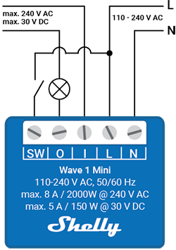 |
|  |
|
Legend
| Terminal | Function | Cable | Function |
|---|---|---|---|
| N | Neutral terminal | N | Neutral wire |
| L | Live terminal (110–240 V AC) | L | Live (110–240 VAC) wire |
| SW | Switch/Push-button input terminal (controls O) | — | — |
| I | Load circuit input terminal | S | S button |
| O | Load circuit output terminal | — | — |
About Z-Wave®
Adding the Device to a Z-Wave® Network (Inclusion)
🔔 Note: All outputs (O, O1, etc.) will briefly turn on/off 1 second each if the device is successfully added/removed.
🔐 Note: For Security 2 (S2) inclusion, enter the 5-digit PIN from the DSK label on the device or packaging.
❗ Do not lose the PIN code.
SmartStart Inclusion
- Scan the Z-Wave QR code on the device using a gateway with SmartStart support.
- Connect the device to power.
- If the blue LED blinks in Mode 1, the device is not yet added.
- The device will automatically join within seconds.
- Blue LED blinks in Mode 2 during inclusion.
- Green LED blinks in Mode 1 upon successful addition.
Inclusion with S Button
- Connect device to power.
- Confirm blue LED blinks in Mode 1.
- Enable "add/remove" mode on the gateway.
- Press and hold S button until LED turns solid blue.
- Release, then press and hold (>2s) until blue LED blinks in Mode 3 → release → starts Learn mode.
- Blue LED blinks in Mode 2 during inclusion.
- Green LED blinks in Mode 1 if successful.
⏱️ Note: Setting mode has a 10-second timeout before returning to Normal mode.
Inclusion with Switch/Push-Button
- Connect device to power.
- Confirm blue LED blinks in Mode 1.
- Enable "add/remove" mode on gateway.
- Toggle the switch/push-button connected to SW terminal 3 times within 3 seconds (must receive 3 on/off signals).
- Blue LED blinks in Mode 2 during inclusion.
- Green LED blinks in Mode 1 if successful.
📌 Learn mode: State allowing device to receive network information from gateway.
Removing the Device from a Z-Wave® Network (Exclusion)
📝 Note: Custom configurations remain intact. Only network membership is removed.
🔔 Note: Outputs briefly flash on/off upon removal.
Removal with S Button
- Connect device to power.
- Confirm green LED blinks in Mode 1 (device is included).
- Enable "add/remove" mode on gateway.
- Press and hold S button until LED turns solid blue.
- Release, then press and hold (>2s) until blue LED blinks in Mode 3 → release → starts Learn mode.
- Blue LED blinks in Mode 2 during removal.
- Blue LED blinks in Mode 1 upon successful removal.
⏱️ Setting mode timeout: 10 seconds
Removal with Switch/Push-Button
- Connect device to power.
- Confirm green LED blinks in Mode 1.
- Enable "add/remove" mode on gateway.
- Toggle switch/push-button on SW terminal 3 times within 3 seconds.
- Blue LED blinks in Mode 2 during removal.
- Blue LED blinks in Mode 1 upon success.
Factory Reset
General
After reset:
- All custom parameters erased
- kWh, associations, routing data cleared
- HOME ID and NODE ID deleted
- Use only if gateway is missing or non-functional
With S Button
- Press and hold S button until LED turns solid blue.
- Press S button repeatedly until LED turns solid red.
- Hold S button (>2s) until red LED blinks in Mode 3 → release → starts reset.
- LED: Solid green (~1s), then blue + red blink rapidly (~2s).
- Blue LED blinks in Mode 1 if successful.
With Switch/Push-Button
⚠️ Only possible within first minute after power-up.
- Connect device to power.
- Toggle switch/push-button on SW terminal 5 times within 3 seconds.
- LED: Solid green (~1s), then blue + red blink rapidly (~2s).
- Blue LED blinks in Mode 1 if successful.
Remote Reset via Gateway Parameter
Use Parameter No. 120 to trigger remote factory reset.
Z-Wave® Security and Device Specific Key (DSK)
The device supports Security 2 (S2) using AES-128 encryption, making Z-Wave one of the most secure IoT platforms.
- Authenticated Control supported
- Out-of-Band DSK for inclusion
- Supports S2 Authenticated, Unauthenticated, and Unsecure inclusion
🔐 When adding via S2-enabled gateway, you must provide the 5-digit PIN from the DSK label on the device or inside packaging.
🖼️ The DSK label includes a QR code for easy scanning.
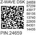
✅ First five digits are highlighted/underlined for easy identification.
🛡️ Joining node obfuscates its public key by setting bytes 1–2 to zero before RF transmission.
🔍 The gateway can scan the QR code to match the obfuscated public key received via RF.
Z-Wave® Parameters
| Parameter | Description | Size | Default | Values & Descriptions |
|---|---|---|---|---|
| 1 – SW (SW1) Switch Type | Defines behavior of SW1 input | 1 Byte | 2 | 0 = momentary switch 1 = toggle (contact closed = ON) 2 = toggle (state changes on switch change) |
| 17 – Restore O (O1) After Power Failure | Save/restore last state after power loss | 1 Byte | 0 | 0 = restore last state 1 = remains OFF |
| 19 – Auto OFF Timer (O1) | Schedule automatic OFF after ON | 2 Bytes | 0 | 0 = Disabled 1–32535 = seconds or milliseconds (see Param 25) |
| 20 – Auto ON Timer (O1) | Schedule automatic ON after OFF | 2 Bytes | 0 | 0 = Disabled 1–32535 = seconds or milliseconds |
| 23 – Contact Type (NO/NC) | Relay contact type | 1 Byte | 0 | 0 = NO (Normally Open) 1 = NC (Normally Closed) |
| 25 – Timer Unit (s/ms) | Set timer resolution | 1 Byte | 0 | 0 = seconds 1 = milliseconds |
| 91 – Water Alarm Response | Action on water alarm | 4 Bytes | 0 | 0 = no action 1 = open relay 2 = close relay |
| 92 – Smoke Alarm Response | Action on smoke alarm | 4 Bytes | 0 | 0 = no action 1 = open relay 2 = close relay |
| 93 – CO Alarm Response | Action on CO alarm | 4 Bytes | 0 | 0 = no action 1 = open relay 2 = close relay |
| 94 – Heat Alarm Response | Action on heat alarm | 4 Bytes | 0 | 0 = no action 1 = open relay 2 = close relay |
| 120 – Factory Reset | Trigger factory reset | 1 Byte | 0 | 0 = no reset 1 = perform reset |
| 201–203 – Serial Number Parts | Read-only serial parts | 4 Bytes each | Device-specific | 0x00000000 – 0x7FFFFFFF |
💡 Parameters 201–203 are read-only and may be hidden under "Advanced" tag.
Z-Wave® Command Classes
- ASSOCIATION_V2 [S0, S2]*
- ASSOCIATION_GRP_INFO_V3 [S0, S2]*
- BASIC_V2 [S0, S2]*
- SWITCH_BINARY_V2 [S0, S2]*
- CONFIGURATION_V4 [S0, S2]*
- DEVICE_RESET_LOCALLY_V1 [S0, S2]*
- FIRMWARE_UPDATE_MD_V5 [S0, S2]*
- INDICATOR_V3 [S0, S2]*
- MANUFACTURER_SPECIFIC_V2 [S0, S2]*
- MULTI_CHANNEL_ASSOCIATION_V3 [S0, S2]*
- NOTIFICATION_V8 [S0, S2]*
- POWERLEVEL_V1 [S0, S2]*
- SECURITY_V1
- SECURITY_2_V1
- SUPERVISION_V1
- TRANSPORT_SERVICE_V2
- VERSION_V3 [S0, S2]*
- ZWAVEPLUS_INFO_V2
Supported under S0 and S2 security levels
Z-Wave® Notifications Command Class
| Field | Value |
|---|---|
| Comment | Overheat detected |
| Notification Type Name | Heat Alarm |
| Type – Value | 0x04 |
| Event | State |
| Name | Overheat detected |
| Name – Value | 0x02 |
| Version | V2 |
| Device Specific | Yes |
| LED Signalisation | Check LED table |
| Device Reaction | Switch OFF all outputs + send notification |
| Restore Actions | Power cycle, short S button press, or press any SW button |
Z-Wave® Associations
Association Group 1 – Lifeline Group
- Max 9 nodes
- Reserved for controllers (gateways, remotes)
- Reports triggered:
INDICATOR_REPORT: LED statusDEVICE_RESET_LOCALLY_NOTIFICATION: Upon requestSWITCH_BINARY_REPORT: Status change of O (O1)NOTIFICATION_REPORT: Overheat detected
Association Group 2
- Max 9 nodes
- Linked to SW (SW1) input
- Uses BASIC_SET command class
- Triggers: ON/OFF signal from SW (switch or push-button)
- Sends
BASIC_SET ONorBASIC_SET OFFto associated devices
Association Group 3
- Max 9 nodes
- Linked to SW (SW1) input
- Recommended for push-buttons
- Uses SWITCH_MULTILEVEL commands:
START_LEVEL_CHANGE: Begin dimming/moving shutterSTOP_LEVEL_CHANGE: Stop transition
📌 Recommendation: Limit to ≤5 devices per group to avoid network delays.
Z-Wave® Important Disclaimer
Z-Wave® communication may not always be 100% reliable.
Do not use this device in life-critical applications.
If unrecognized by gateway or misbehaving, manually set device type and confirm gateway supports Z-Wave Plus™ multi-level devices.
Troubleshooting
For help, visit: Support Portal
Compatibility
| Gateway | On/Off | SW On/Off | Notes |
|---|---|---|---|
| Home Assistant | ✅ | ✅ | |
| Fibaro HC3 / Z-Wave Engine 3 | ✅ | ✅ | |
| Homey | ✅ | ✅ | |
| Homee Cube Gen 7 | ✅ | ✅ | |
| Homee Cube Gen 5 | ✅ | ⚪ | Partial |
| SmartThings | ✅ | ✅ | With Shelly Wave edge driver |
| Vera Ezlo | ✅ | ✅ | |
| Cozify | ✅ | ✅ |
📌 Legend:
- ✅ Working / Possible
- ⚪ Partially
- ❌ Not Working / Not Possible
- N/T Not Tested
- TBD To Be Done
Function Meaning
| Function | Meaning / Test Result |
|---|---|
| On/Off | Responds to app UI On/Off command |
| SW On/Off | Reports On/Off changes via SW input |
| Dimming | Responds to app UI dimming command |
| SW Dimming | Reports dimming state change via SW |
| Watts | Reports watts unsolicited |
| kWh | Reports kWh unsolicited |
| Up/Down | Responds to app UI Up/Down command |
| SW Up/Down | Reports Up/Down changes via SW |
| Slats | Responds to slats command |
| SW Slats | Reports slats changes via SW |
| D control | Detached mode: reports single/double press, etc. |
| D Binary | Detached mode: reports binary On/Off via SW |
| Sensor # | Sensor report visible? Type in notes |
Gateway Guides
Find useful guides at the Shelly Knowledge Base
Compliance
- Wave 1 Mini Multilingual EU Declaration of Conformity (2025-07-22)
- Wave 1 Mini UK PSTI ACT Statement of Compliance