Device identification
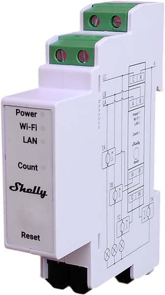
- Device name: Shelly Pro 3EM
- Device model: SPEM-003CEBEU
- Device SSID: ShellyPro3EM-XXXXXX
Short description
Shelly Pro 3EM (The Device) is a DIN rail mountable three-phase energy meter. Enhanced with all the gen2 firmware flexibility and LAN connectivity, it provides professional integrators with additional options for end-customer solutions. It can work standalone in a local LAN and/or Wi-Fi network, or it can also be operated through cloud home automation services through MQTT, HTTP, and WebSocket. All inbound connections support TLS.
The Device reports accumulated energy as well as instantaneous voltage, current, active, and apparent power per phase in real time. It stores data in non-volatile memory that can be retrieved for a period of up to 60 days in 1-minute intervals.
The Device has a real-time clock to keep the correct time if the connection to an SNTP server is lost.
Shelly Pro 3EM can be accessed, set up, and monitored remotely by the User, as well as the Device can access and communicate with an automation system, as long as they are in the same network infrastructure.
The Device has an embedded Web Interface which can be used to monitor and control the device, as well as adjust its settings.
⚠ NOTICE! The Device does not have a built-in relay. Contactor control is provided using a Shelly Pro Addon attached to the Shelly Pro 3EM.
Features
- 4 Quadrant measurement
- DIN rail mounting
- Multiple connection types
- Current transformer connection
- Phase sequence error detection* (option)
- Channel-to-channel calibration**
- No load threshold***
- Optical pulse indication of energy usage
- Real-time clock
- Data logs
- Accuracy Class B (IEC 62053-21)
- Photovoltaic ready
- The Device has phase sequence error detection circuits. This detection works on phase voltages and considers only the zero crossings. The regular succession of these zero-crossing events is Phase A followed by Phase B followed by Phase C. If the sequence of zero-crossing events is, instead, Phase A followed by Phase C followed by Phase B, then a
phase_sequenceerror is reported when the Phase sequence error detection option is enabled.
** At least 500 W load is required for each channel.
*** In case the total load for the three channels drops below 30 VA per channel, the measured power level will be displayed, but no consumed energy will be accumulated to the energy statistics and a
No load thresholdnotification will be displayed in the Device web interface and the mobile application.
Main applications
- Residential
- MDU (Multi Dwelling Units - apartments, condominiums, hotels, etc.)
- Light commercial (small office buildings, small retail/restaurant/gas station, etc.)
- Agricultural (farms, barns, silos, etc.)
- Government/municipal
- University/college
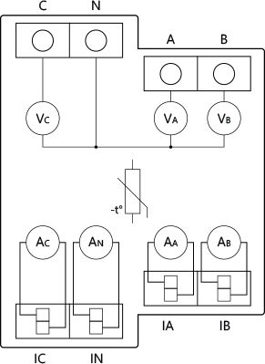
Simplified internal schematics
Device electrical interfaces
Inputs
- 4 line inputs on screw terminals: 3 L and 1 N
- 4 current transformer inputs: 3 for L current measurements and 1 for N current measurement
Ethernet port
- 1 RJ45 connector
⚠ CAUTION! Plug in or unplug the LAN cable only when the Device is powered off! The LAN cable connector must not be metallic in the parts touched by the user to plug in or unplug the cable.
Add-on interface
- Shelly proprietary serial interface
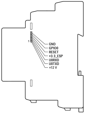
⚠ CAUTION! High voltage on the add-on interface when the Device is powered!
Connectivity
- Ethernet
- Wi-Fi
- Bluetooth
Each connectivity option can be enabled or disabled by the user.
Safety features
- Internal temperature sensing and reporting
Supported load types
- Resistive (incandescent bulbs, heating devices)
- Capacitive (LED light drivers, capacitor banks, electronic equipment, motor start capacitors)
- Inductive (transformers, fans, refrigerators, air-conditioners)
User interface
Inputs
- One tactile dome button
- Press briefly to toggle the state of the relay in the attached Shelly Pro 3EM Switch Add-on.
- Press and hold for 5 sec to activate Device AP.
- Press and hold for 10 sec to factory reset.
Outputs
- LED indication
- Power: Red light if the power supply is connected.
- Wi-Fi (varies):
- Blue light if in AP mode.
- Red light if in STA mode, and not connected to a Wi-Fi network.
- Yellow light if in STA mode, and connected to a Wi-Fi network. Not connected to Shelly Cloud or Shelly Cloud disabled.
- Green light if in STA mode, and connected to a Wi-Fi network and the Shelly Cloud.
- Flashing Red/Blue if OTA update is in progress.
- LAN: Green light if LAN is connected.
- Count: Red light flashing when the Device is measuring energy according to settings, with frequency dependent on the energy flowing through the measured circuit.
Specifications
| Type | Value |
|---|---|
| Physical | |
| Size (HxWxD): | 94x19x69 ±0.5 mm / 3.70x0.75x2.71 ±0.02 in |
| Weight: | 62 ±1 g / 2.19 ±0.05 oz |
| Mounting: | DIN rail |
| Screw terminals max torque: | 0.4 Nm / 4.43 lbin |
| Conductor cross section: | 0.5 to 2.5 mm² / 20 to 14 AWG (solid, stranded, and bootlace lugs) |
| Conductor stripped length: | 6 to 7 mm / 0.24 to 0.28 in |
| Shell material: | Plastic |
| Color: | White |
| Environmental | |
| Ambient temperature: | -20 °C to 40 °C / -5 °F to 105 °F |
| Humidity: | 30 % to 70 % RH |
| Max. altitude: | 2000 m / 6562 ft |
| Electrical | |
| Power supply voltage AC: | 100 - 260 V, 50/60 Hz |
| Power supply voltage DC: | N/A |
| Power consumption: | < 3 W |
| External protection: | Tripping characteristic B or C, 16A max. rated current, min. 6 kA interrupting rating, energy limiting class 3 |
| Sensors, meters | |
| Internal-temperature sensor: | Yes |
| Voltmeters (RMS for each phase): | 100 - 260 V |
| Voltmeters accuracy: | ±1 % |
| Ammeters (RMS via CT for each phase and the Neutral): | 0 - 120 A |
| Compatible CT: | CT 120A |
| Ammeters accuracy: | ±1 % (2 - 120 A), ±2 % (1 - 2 A), ±5 % (0 - 1 A) |
| Power and energy meters: | Active and apparent power, Active and apparent energy, Power factor, Fundamental active and fundamental reactive energy |
| Channel-to-channel calibration minimum load: | 500 W per channel |
| No load threshold: | 30 VA per channel |
| Measurement data storage: | At least 60 days of 1 min data resolution |
| Data export: | CSV for PQ recorded values, JSON format export through RPC |
| Radio | |
| RF band: | 2400 - 2495 MHz |
| Max. RF power: | <20 dBm |
| Wi-Fi protocol: | 802.11 b/g/n |
| Wi-Fi Range: | Up to 30 m / 100 ft indoors and 50 m / 160 ft outdoors (Depends on local conditions) |
| Bluetooth Protocol: | 4.2 |
| Bluetooth Range: | Up to 10 m / 33 ft indoors and 30 m / 100 ft outdoors (Depends on local conditions) |
| MCU | |
| CPU: | ESP32-D0WDQ6 |
| Flash: | 16 MB |
| Firmware capabilities | |
| Webhooks (URL actions): | 20 with 5 URLs per hook |
| Scripting: | Yes |
| MQTT: | Yes |
| CoAP: | No |
Basic wiring diagrams
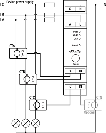
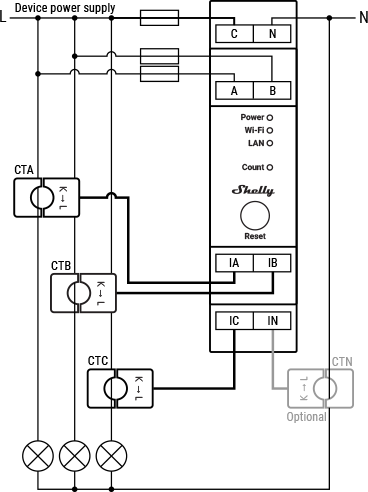
Legend
| Terminals | Description | Wires | Description |
|---|---|---|---|
| A | Phase A input | LA | Phase A live (110-240 V) wire |
| B | Phase B input | LB | Phase B live (110-240 V) wire |
| C | Phase C and power supply input | LC | Phase C live (110-240 V) wire |
| N | Neutral terminal | L | Mono-phase live (110-240 V) wire |
| IA | Phase A current transformer input | N | Neutral wire |
| IB | Phase B current transformer input | Current transformers | |
| IC | Phase C current transformer input | CTA | Phase A current transformer |
| IN | Neutral current transformer input | CTB | Phase B current transformer |
| CTC | Phase C current transformer | ||
| CTN | Neutral current transformer (Optional. Not included) |
Shelly Smart Control
Shelly Web user interface
Troubleshooting
...
Components and APIs
Compliance
Shelly Pro 3EM multilingual EU declaration of conformity 2025-07-23
Shelly Pro 3EM 120A UK PSTI ACT Statement of compliance
Shelly Pro 3EM AU NZ Certificate for Suitability
Compliance archive
Shelly Pro 3EM multilingual EU declaration of conformity 4 2023-04-25