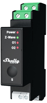
Shelly Wave Pro 2PM
Note: The product line known as "Shelly Qubino Wave" will now be referred to as "Shelly Wave". This name change will not impact the functionality of any devices. The only modification will be the use of the new name in all future documentation.
Device Identification
- Device: Wave Pro 2PM
- USA Part number / Ordering Code: QPSW-0A2P16US
- Z-Wave Product type ID:
0x0002 - Z-Wave Product ID:
0x008D - Z-Wave Manufacturer: Shelly Europe Ltd.
- Z-Wave Manufacturer ID:
0x0460
Terminology
- Device: In this document, the term “Device” refers to the Shelly Qubino device that is the subject of this guide.
- Gateway: A Z-Wave® gateway, also called a Z-Wave® controller, primary controller, hub, etc., serves as the central hub for a Z-Wave® smart home network. The term "gateway" is used here.
- S button: The Z-Wave® Service button located on Z-Wave® devices, used for inclusion, exclusion, and factory reset. The term "S button" is used throughout.
Short Description
The Shelly Wave Pro 2PM is a DIN rail-mountable, two-channel smart switch with power measurement. It controls two independent electrical loads up to 16 A per channel (25 A total). Compatible with switches (default) and push-buttons.
Switch / Push-Button Connected to Input Terminal SW (SW1)
Switch Connected to SW1 (Default)
Each toggle changes output O1 state: On → Off → On, etc.
- Single toggle: Change O1 state and send command to associated devices in groups 2 and 3 (see Z-Wave Association).
- Double toggle (within 500ms): Interpreted as double action; send command to dimmers, shutters, etc., in groups 2 and 3.
Switch-Memory Connected to SW1
- Close contact: Set O1 to ON and send command to group 2 & 3.
- Open contact: Set O1 to OFF and send command to group 2 & 3.
Push-Button Connected to SW1
Each press toggles O1 state: On → Off → On, etc.
- Short press: Toggle O1 state and send command to groups 2 & 3.
- Hold: Send command to group 3.
- Release: Send command to group 3.
Switch / Push-Button Connected to Input Terminal SW2
Switch Connected to SW2 (Default)
Each toggle changes output O2 state: On → Off → On, etc.
- Single toggle: Change O2 state and send command to groups 4 and 5.
- Double toggle (within 500ms): Interpreted as double action; send command to dimmers, shutters, etc., in groups 4 and 5.
Switch-Memory Connected to SW2
- Close contact: Set O2 to ON and send command to group 4 & 5.
- Open contact: Set O2 to OFF and send command to group 4 & 5.
Push-Button Connected to SW2
Each press toggles O2 state: On → Off → On, etc.
- Short press: Toggle O2 state and send command to groups 4 & 5.
- Hold: Send command to group 4.
- Release: Send command to group 5.
Switching On/Off Load Connected to O (O1)
Load connected to O1 can be switched via:
- Z-Wave command
- Automatic switching via Parameters 19 and 20
- Pressing the switch/push-button SW1 (toggles state)
Switching On/Off Load Connected to O2
Load connected to O2 can be switched via:
- Z-Wave command
- Automatic switching via Parameters 21 and 22
- Pressing the switch/push-button SW2 (toggles state)
Main Applications
- Residential
- MDU (Multi Dwelling Units – apartments, condos, hotels, etc.)
- Light commercial (small offices, retail, restaurants, gas stations, etc.)
- Government / Municipal
- University / College
Integrations
Shelly Wave devices are built on Z-Wave, the world’s leading smart home technology. They work with all certified gateways supporting the Z-Wave protocol.
We regularly test compatibility with various Z-Wave gateways to ensure full functionality.
Simplified Internal Schematics
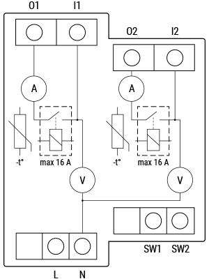
Device Electrical Interfaces
Inputs
- 2 switch/button inputs on screw terminals
- 3 power supply inputs on screw terminals: N (+), L (Ʇ)
Outputs
- 2 relay outputs with power measurement on screw terminals
Connectivity
Z-Wave: Unsecure, S0 Security, S2 Unauthenticated Security, S2 Authenticated Security
Safety Features
Overheat Protection
- If temperature exceeds 80°C for >5 seconds:
- Turns off relay
- Sends Notification Report ("Overheat detected") to gateway
- LED reacts accordingly (see blinking modes)
- Reset by: Power cycle, short S button press, or pressing any switch/push-button.
✅ Overheat protection is always active and cannot be disabled.
See more: Notification for Overheat Detected
Over-Current Protection
- If current exceeds 16A + 10% (>17.6A) for >5 seconds:
- Turns off relay
- Sends Notification Report ("Over-current detected")
- LED reacts accordingly
- Reset by: Power cycle, short S button press, or pressing any switch/push-button.
✅ Over-current protection is always active and cannot be disabled.
See more: Notification for Over-current Detected
Over-Voltage Protection
- Valid for 230 V AC supply.
- If voltage exceeds 278 V AC (>240V +15%) for >5 seconds:
- Turns off relay
- Sends Notification Report ("Over-voltage detected")
- LED reacts accordingly
- Reset by: Power cycle, short S button press, or pressing any switch/push-button.
✅ Over-voltage protection is always active and cannot be disabled.
See more: Notification for Over-voltage Detected
Supported Load Types
- Resistive (incandescent bulbs, heating devices)
- Capacitive (capacitor banks, electronic equipment, motor start capacitors)
- Inductive with RC Snubber (LED drivers, transformers, fans, refrigerators, air conditioners)
User Interface
S Button and Operating Modes
- Normal mode
- Setting in progress mode
- Setting mode (with S button)
Settings mode allows actions like inclusion, exclusion, or factory reset. Automatically reverts to Normal mode after completion.
Entering Setting Mode:
- Quickly press and hold S button until LED turns solid blue.
- Additional quick press cycles through menu.
- Menu timeout: 10 seconds before returning to Normal mode.
S Button Functions
- Manually add device to Z-Wave network
- Manually remove device from Z-Wave network
- Factory reset device
LED Signalisation
| Status | LED Behavior |
|---|---|
| Removed/Excluded | Blinking blue in Mode 1 (10 min after power-up or S button press) |
| Added/Included | Blinking green in Mode 1 (10 min after power-up or S button press) |
| Factory Reset & Reboot | Solid green (~1 sec), then blue/red blink (0.1s on/off, ~2 sec) |
| Adding/Removing | Blinking blue in Mode 2 |
| OTA Update | Blinking blue and red in Mode 2 |
| Power Supply Check | Blinking blue and red in Mode 5 |
| Menu Selected (Add/Remove) | Solid blue (max 10 sec) |
| Add/Remove in Progress | Blinking blue in Mode 3 |
| Menu Selected (Factory Reset) | Solid red (max 10 sec) |
| Factory Reset in Progress | Blinking red in Mode 3 |
| Alarm Mode – Overcurrent | Red blinking 1×: 0.2s on, 0.2s off, 2s off |
| Alarm Mode – Overheat | Red blinking 2×: 0.2s on/off repeated |
| Alarm Mode – Power Fault | Red blinking 3×: 0.2s on/off repeated |
| Alarm Mode – Overvoltage | Red blinking 7×: 0.2s on/off repeated |
LED Blinking Modes
| Mode | Behavior |
|---|---|
| Mode 1 | 0.5s On / 2s Off |
| Mode 2 | 0.5s On / 0.5s Off |
| Mode 3 | 0.1s On / 0.1s Off |
| Mode 4 | (1–6 times: 0.2s On/Off) + 2s Off |
| Mode 5 | 0.2s On (blue) / 0.2s On (red) |
Specifications
Error rendering macro 'excerpt-include': User does not have permission to view the page 'DEV:Technical Specifications'.
Basic Wiring Diagram
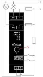
Legend
| Terminal | Function | Wire | Function |
|---|---|---|---|
| N | Neutral terminal | N | Neutral wire |
| L | Live terminal (110–240 V AC) | L | Live (110–240 VAC) wire |
| SW1 | Switch/push-button input (controls O1) | — | — |
| SW2 | Switch/push-button input (controls O2) | — | — |
| I1 | Input terminal for Load Circuit 1 | — | — |
| I2 | Input terminal for Load Circuit 2 | — | — |
| O1 | Output terminal for Load Circuit 1 | — | — |
| O2 | Output terminal for Load Circuit 2 | — | — |
About Z-Wave®
Adding the Device to a Z-Wave® Network (Inclusion)
⚠️ All outputs (O, O1, O2) will briefly turn on/off during successful addition/removal.
SmartStart Inclusion
- Scan QR code on device label using gateway app.
- Add DSK to provisioning list.
- Connect device to power.
- If blue LED blinks in Mode 1 → not added yet.
- Auto-inclusion begins within seconds.
- Blue LED blinks in Mode 2 during inclusion.
- Green LED blinking in Mode 1 = success.
Adding with S Button
- Power on device.
- Confirm blue LED blinks in Mode 1.
- Enable add/remove mode on gateway.
- Press and hold S button until LED turns solid blue.
- Release, then press and hold (>2s) until LED blinks in Mode 3 → starts Learn mode.
- Blue LED blinks in Mode 2 during inclusion.
- Green LED in Mode 1 = success.
⏳ Setting mode timeout: 10 seconds.
Adding with Switch/Push-Button
- Power on device.
- Confirm blue LED in Mode 1.
- Enable add/remove mode on gateway.
- Toggle switch/push-button connected to any SW terminal 3 times within 3 seconds → enters Learn mode.
- Blue LED blinks in Mode 2 during inclusion.
- Green LED in Mode 1 = success.
🔍 Learn mode: State allowing device to receive network info from gateway.
Removing the Device from a Z-Wave® Network (Exclusion)
⚠️ Removes device from network but preserves custom settings.
Removing with S Button
- Power on device.
- Confirm green LED in Mode 1 → device is added.
- Enable add/remove mode on gateway.
- Press and hold S button until LED turns solid blue.
- Release, then press and hold (>2s) until LED blinks in Mode 3 → starts Learn mode.
- Blue LED blinks in Mode 2 during removal.
- Blue LED in Mode 1 = success.
Removing with Switch/Push-Button
- Power on device.
- Confirm green LED in Mode 1.
- Enable add/remove mode on gateway.
- Toggle switch/push-button 3 times within 3 seconds → enters Learn mode.
- Blue LED blinks in Mode 2 during removal.
- Blue LED in Mode 1 = success.
Factory Reset
🛑 After reset: All custom parameters reset. HOME ID and NODE ID deleted.
With S Button
- Press and hold S button until LED turns solid blue.
- Press S button repeatedly until LED turns solid red.
- Hold S button (>2s) until red LED blinks in Mode 3 → starts reset.
- During reset: solid green for ~1s, then blue/red blink in Mode 3 (~2s).
- Blue LED in Mode 1 = success.
With Switch/Push-Button
❗ Only possible within first minute after power-up.
- Power on device.
- Toggle switch/push-button 5 times within 3 seconds.
- During reset: solid green (~1s), then blue/red blink in Mode 3 (~2s).
- Blue LED in Mode 1 = success.
Remote Reset via Parameter 120
Set Parameter No. 120 to 1431655765 (hex 0x55555555) to trigger remote factory reset.
💡 After reset, value auto-resets to 0.
Z-Wave® Security and Device Specific Key (DSK)
The device supports Security 2 (S2) using Strong AES 128 encryption — the most secure IoT platform available.
- Supports: S2 Authenticated, S2 Unauthenticated, and Unsecure inclusion.
- For S2 inclusion: Enter PIN (first 5 digits) from DSK label on device or packaging.
🔐 Do not lose or remove the DSK label.
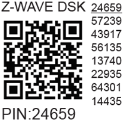
The DSK may be used for out-of-band (OOB) authentication via QR code scanning.
Z-Wave® Parameters
| Parameter | Description | Size | Default | Values |
|---|---|---|---|---|
| 1 – SW (SW1) Switch Type | Defines behavior of SW1 input | 1 Byte | 2 | 0: momentary, 1: toggle (closed=ON), 2: toggle (state change) |
| 2 – SW2 Switch Type | Defines behavior of SW2 input | 1 Byte | 2 | 0: momentary, 1: toggle (closed=ON), 2: toggle (state change) |
| 6 – Inputs SW1 & SW2 Swap | Swap operations without rewiring | 1 Byte | 0 | 0: default (SW1→O1, SW2→O2), 1: swapped |
| 16 – Outputs O1 & O2 Swap | Swap relay outputs | 1 Byte | 0 | 0: default (O1 open, O2 close), 1: reversed |
| 17 – Restore O1 State After Power Failure | Save last state after power loss | 1 Byte | 0 | 0: restore, 1: remain off |
| 18 – Restore O2 State After Power Failure | Save last state after power loss | 1 Byte | 0 | 0: restore, 1: remain off |
| 19 – O1 Auto OFF Timer | Auto-off after set time | 2 Bytes | 0 | 0: disabled, 1–32535: seconds/ms (see P25) |
| 20 – O1 Auto ON Timer | Auto-on after set time | 2 Bytes | 0 | 0: disabled, 1–32535: seconds/ms (see P25) |
| 21 – O2 Auto OFF Timer | Auto-off after set time | 2 Bytes | 0 | 0: disabled, 1–32535: seconds/ms (see P26) |
| 22 – O2 Auto ON Timer | Auto-on after set time | 2 Bytes | 0 | 0: disabled, 1–32535: seconds/ms (see P26) |
| 23 – O1 Contact Type (NO/NC) | Relay contact type | 1 Byte | 0 | 0: NO, 1: NC |
| 24 – O2 Contact Type (NO/NC) | Relay contact type | 1 Byte | 0 | 0: NO, 1: NC |
| 25 – Timer Units (O1) | Seconds or milliseconds | 1 Byte | 0 | 0: seconds, 1: milliseconds |
| 26 – Timer Units (O2) | Seconds or milliseconds | 1 Byte | 0 | 0: seconds, 1: milliseconds |
| 36 – O1 Power Report Threshold (%) | Min % change to report | 1 Byte | 50 | 0: disabled, 1–100% |
| 37 – O2 Power Report Threshold (%) | Min % change to report | 1 Byte | 50 | 0: disabled, 1–100% |
| 39 – Min Time Between O1 Reports (s) | Interval between reports | 1 Byte | 30 | 0: disabled, 1–120s |
| 40 – Min Time Between O2 Reports (s) | Interval between reports | 1 Byte | 30 | 0: disabled, 1–120s |
| 91 – Water Alarm Response | Action on water alarm | 4 Bytes | 0 | 0: no action, 1: open relay, 2: close relay |
| 92 – Smoke Alarm Response | Action on smoke alarm | 4 Bytes | 0 | 0: no action, 1: open relay, 2: close relay |
| 93 – CO Alarm Response | Action on CO alarm | 4 Bytes | 0 | 0: no action, 1: open relay, 2: close relay |
| 94 – Heat Alarm Response | Action on heat alarm | 4 Bytes | 0 | 0: no action, 1: open relay, 2: close relay |
| 120 – Factory Reset | Trigger factory reset | 4 Bytes | 0 | 0: no reset, 1431655765 (0x55555555) |
| 201–203 – Serial Number Parts | Read-only serial parts | 4 Bytes each | Device-specific | 0x00000000 – 0x7FFFFFFF |
⚠️ Parameters 201–203 are advanced and may be hidden.
Z-Wave® Command Classes
- ASSOCIATION_V2 [S0, S2]*
- ASSOCIATION_GRP_INFO_V3 [S0, S2]*
- BASIC_V2 [S0, S2]*
- SWITCH_BINARY_V2 [S0, S2]*
- CONFIGURATION_V4 [S0, S2]*
- DEVICE_RESET_LOCALLY_V1 [S0, S2]*
- FIRMWARE_UPDATE_MD_V5 [S0, S2]*
- INDICATOR_V3 [S0, S2]*
- MANUFACTURER_SPECIFIC_V2 [S0, S2]*
- METER_V6 [S0, S2]*
- MULTI_CHANNEL_V4 [S0, S2]*
- MULTI_CHANNEL_ASSOCIATION_V3 [S0, S2]*
- NOTIFICATION_V8 [S0, S2]*
- POWERLEVEL_V1 [S0, S2]*
- SECURITY_V1
- SECURITY_2_V1
- SUPERVISION_V1
- TRANSPORT_SERVICE_V2
- VERSION_V3 [S0, S2]*
- ZWAVEPLUS_INFO_V2
Endpoint 1 & 2 support similar classes except
FIRMWARE_UPDATE,POWERLEVEL, andSECURITY.
Z-Wave® Notifications Command Class
Overheat Detected
- Type: Heat Alarm (
0x04) - Event: State
- Name: Overheat detected (
0x02) - Version: V2
- LED: Mode 4 (2x blink)
- Action: Switch OFF all outputs, send notification
- Restore: Power cycle, S button press, or switch press
Over-current Detected (O1)
- Type: Power Management (
0x08) - Event: State
- Name: Over-current detected (
0x06) - Version: V3
- LED: Mode 4 (1x blink)
- Action: Switch OFF O1, send notification
- Restore: Power cycle, S button press, or switch press
AC Mains Disconnected
- Type: Power Management (
0x08) - Event: State
- Name: AC mains disconnected (
0x02) - Version: V2
- LED: Mode 4 (1x blink)
- Action: Switch OFF all outputs, send notification
- Restore: Power cycle, S button press, or switch press
Over-voltage Detected
- Type: Power Management (
0x08) - Event: State
- Name: Over-voltage detected (
0x07) - Version: V3
- LED: Mode 4 (7x blink)
- Action: Switch OFF all outputs, send notification
- Restore: Power cycle, S button press, or switch press
Z-Wave® Associations
Root Device
Group 1 (Lifeline): Gateway only. Reports status and triggers:
INDICATOR_REPORTDEVICE_RESET_LOCALLY_NOTIFICATIONSWITCH_BINARY_REPORT(all outputs)NOTIFICATION_REPORT: Overheat, Overcurrent (sum), Overvoltage, AC disconnectMETER_REPORT: Power consumption (O1+O2) based on P36–P43
Group 2: SW1 → sends
BASIC_SET ON/OFFto associated deviceGroup 3: SW1 → sends
SWITCH_MULTILEVEL_START_LEVEL_CHANGEorSTOPGroup 4: SW2 → sends
BASIC_SET ON/OFFGroup 5: SW2 → sends
SWITCH_MULTILEVEL_START_LEVEL_CHANGEorSTOP
Endpoint 1 (O1)
- Group 1: Reports O1 status, overcurrent, power usage
- Group 2: SW1 →
BASIC_SET - Group 3: SW1 →
SWITCH_MULTILEVEL_START/STOP(recommended: push-button)
Endpoint 2 (O2)
- Group 1: Reports O2 status, overcurrent, power usage
- Group 2: SW2 →
BASIC_SET - Group 3: SW2 →
SWITCH_MULTILEVEL_START/STOP(recommended: push-button)
Z-Wave® Important Disclaimer
Z-Wave® communication may not be 100% reliable. Do not rely solely on this device for life-critical or high-value applications. If unrecognized, manually adjust device type and confirm gateway supports Z-Wave Plus™ multi-level devices.
Troubleshooting
Visit our support portal: Support
Compatibility with Gateways
| Gateway | On/Off 1 | On/Off 2 | SW1 On/Off | SW2 On/Off | W 1 | W 2 | kWh | Notes |
|---|---|---|---|---|---|---|---|---|
| Home Assistant | ✓ | ✓ | ✓ | ✓ | ✓ | ✓ | ✓ | |
| Fibaro HC3 / Z-Wave Engine 3 | ✓ | ✓ | ✓ | ✓ | ✓ | ✓ | ✓ | |
| Homey | ✓ | ✓ | ✓ | ✓ | ✓ | ✓ | ✓ | *H |
| Homee Cube Gen 7 | ✓ | ✓ | ✓ | ✓ | ✓ | ✓ | ✓ | |
| Homee Cube Gen 5 | ✓ | ✓ | P*1 | P*1 | ★*2 | ★*2 | ★*2 | *1, *2 |
| SmartThings | ✓ | ✓ | ✓ | ✓ | ✓ | ✓ | ✓ | With Shelly Wave edge driver |
| Vera Ezlo | ✓ | ✓ | ✓ | ✓ | ✓ | ✓ | ✓ | |
| Cozify | ✓ | ✓ | ✓ | ✓ | ✓ | ✓ | ✓ |
Legend:
- ✓: Working
- ★: Not reported in UI
- P: Partially
- H: Issue solvable via this solution
Gateway Guides
Useful guides: Shelly Knowledge Base
Compliance
- Shelly Wave Pro 2PM Multilingual EU Declaration of Conformity
- Wave Pro 2PM UK PSTI ACT Statement of Compliance